98 engineering records across six areas, including board designs, firmware modules, prototypes and studies. Each record identifies its scope and development stage.
Search by application or technology. Selected records include source-code excerpts, flow diagrams and technical notes.
98 records · All six areas
Open a record for technical notes and supporting material.
Hardware and PCB / 9 records
Record 005 / Hardware and PCB
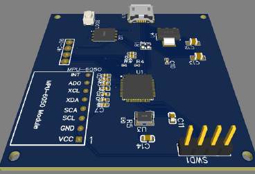
RP2040 interface PCB
PCB design
An RP2040 interface board combines controller connections, power and signal interfaces. Routing and assembly views document the component layout and connector placement.
Assembly design rendering, not a photograph of a manufactured board.Technical notes and images
Board interfaces and placement
The RP2040 design covers controller connections, power and signal interfaces. Routing and assembly views show component placement and connector arrangement.
Project design or interface view — RP2040 interface PCB
Record 029 / Hardware and PCB
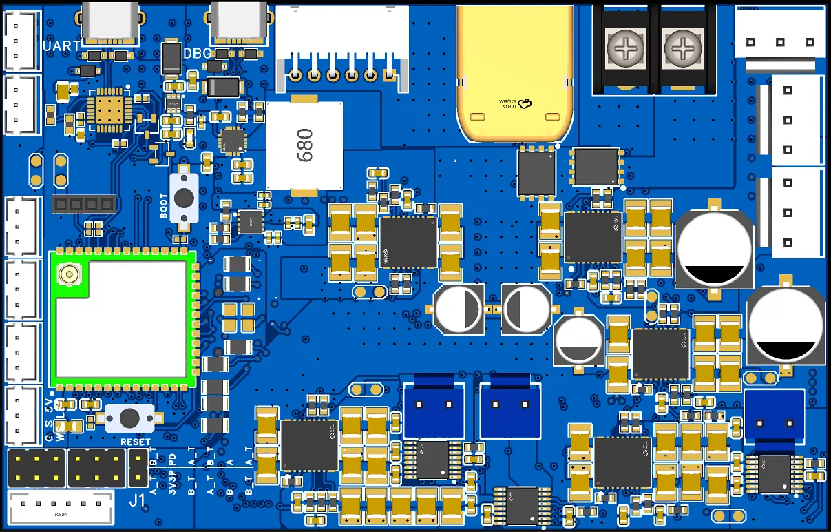
Six-layer controller PCB
Limited public overview
A six-layer controller board for six actuators, sensor inputs, ESP32 control and battery management.
Six-layer PCBSix actuatorsSensorsESP32BMS
Assembly design view. Circuit and firmware details are not shared.Technical notes and images
Only this assembly view and the high-level scope are shared. Circuit and firmware details are not public.
Record 042 / Hardware and PCB
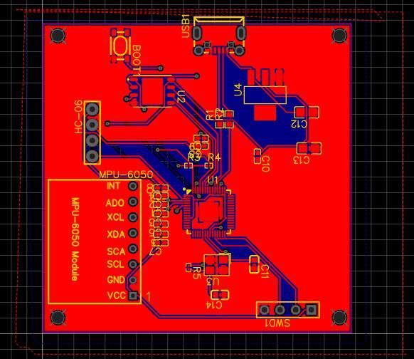
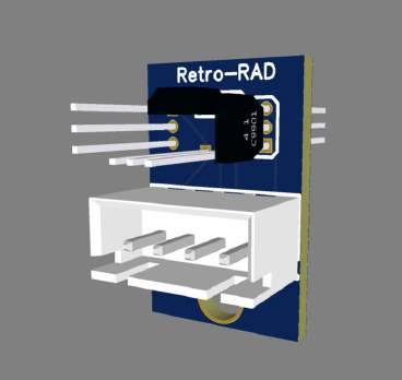
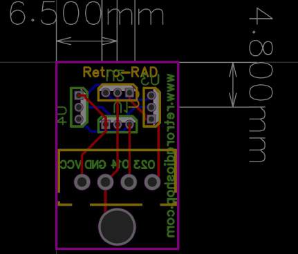
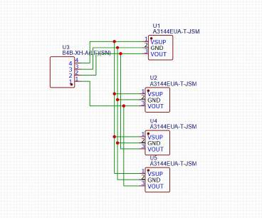
Four channel Hall sensor PCB
PCB design
Four-channel Hall PCB design, with related firmware showing how two magnetic inputs control an FM tuning offset.
Hall sensorsPCB layoutSensor interfaces
Four-channel Hall sensor PCB — original PCB assembly design viewRelated firmware example: Related firmware: recognising magnetic knob movement
Firmware flow
Related firmware: recognising magnetic knob movement
Related two-input magnetic-knob firmware, not proven firmware for the four-channel PCB.
Result · No — ignore transitionRemember the current input state
Compare the previous and current two-input states. Accept only a forward or reverse transition, optionally reverse its sign and accumulate it. Always remember the new state.
The selected variant has no timed Hall debounce or calibration. Accepted transitions contribute directly; they are not divided by four.
Read the implementation
Selected source excerpt · selected source lines 156–169. Source inspection is not a hardware test.
Collect pending movement, update the offset and calculate a target frequency. If the result is beyond a band edge, wrap to the opposite boundary before requesting the tune.
The excerpt demonstrates the requested frequency calculation and boundary wrapping, not calibrated tuning accuracy or PCB operation.
Read the implementation
Selected source excerpt · selected source lines 236–257. Source inspection is not a hardware test.
The reviewed two-input version samples the A/B state when either input changes. It combines the previous and current states into a lookup-table index. Only +1 or −1 results change the pending count; unchanged states and invalid jumps are ignored. Direction can be reversed in configuration.
Frequency offset and wrapping
The main loop copies and clears the pending count with interrupts temporarily disabled. It adds that signed count to totalSteps, then requests baseMHz + totalSteps × 0.2 MHz. An out-of-band request wraps between 88 and 108 MHz. The code counts each accepted transition directly; it does not divide four transitions into one detent.
Filtering the potentiometer, not the Hall edges
The potentiometer uses an exponential moving average with alpha 0.15. Its base frequency changes only after a 0.05 MHz difference. This selected Hall decoder has no timed debounce gate. Other supplied variants use different decoding methods; their filename suffixes do not establish which was the final hardware version.
Board and firmware evidence
The original project record establishes a four-channel PCB design. The supplied tuning example uses two digital Hall inputs, so it is shown as related magnetic-knob firmware. The inspected files do not prove that this version runs on the pictured four-channel board.
Project design or interface view — Four channel Hall sensor PCBProject design or interface view — Four channel Hall sensor PCB
Record 043 / Hardware and PCB
DRV8833 dual motor driver circuit
Circuit design
A dual motor driver circuit based on the DRV8833, with the associated control and power connections.
DRV8833Motor driversCircuit design
Technical notes and images
Control and power
The circuit brings motor-load current and controller signals into the same design.
DRV8833 connections
The DRV8833 circuit defines the motor, power and control connections around the driver.
Motor driver interface
The circuit defines the electrical interface between controller commands and motor drive.
Record 059 / Hardware and PCB
CAN keypad and relay controller PCBs
PCB and firmware development
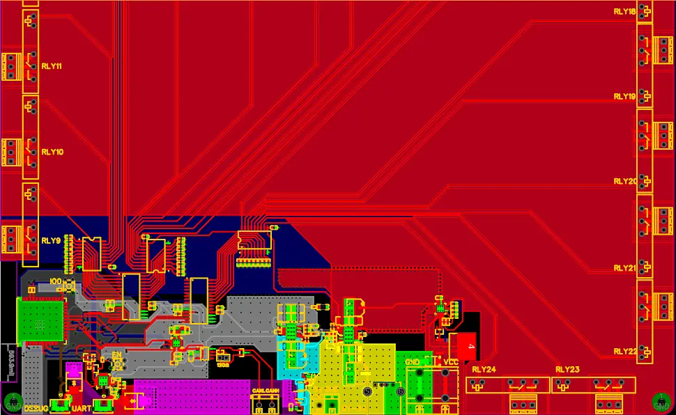
A two-board control system separates the operator’s keypad from the relay outputs. The handheld unit sends key events over CAN; the receiver maps each event to the corresponding relay.
CAN relay receiver PCB layout. Hardware validation is not established by this design view.
System flow
How a key controls an output
Read the keypadCapture the operator’s key event.
Send a CAN commandCarry the event to the receiver.
Map the commandChoose the corresponding relay output.
Apply the outputUpdate the output for press or release.
Technical notes and images
Operator-side keypad
The handheld side scans a keypad and translates user actions into CAN frames. This lets the control interface occupy a different physical location from the board connected to external actuators.
Relay command mapping
The receiver decodes the commands and applies a defined relay mapping. The layout image shows the output board's routing and relay connections, connecting the firmware task with the physical electrical interfaces.
Key-release handling
Key release is part of the command handling. A useful control interface must describe both the start of a requested action and the change when the operator releases the key.
Record 064 / Hardware and PCB
Embedded circuit and schematic package
Circuit design
A circuit and schematic package documenting an embedded system and its electrical interfaces.
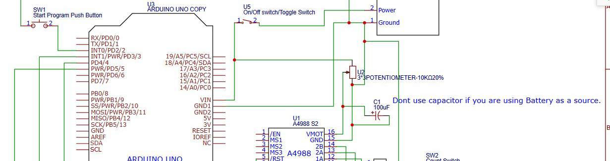
Project design or interface view — Embedded circuit and schematic packageTechnical notes and images
Controller and driver connections
The schematic brings the controller, driver and power connections into a common view. The drawing identifies the boundary between the Arduino's control signals and the motor driver's connections.
Operator controls
A start program push button, power switch and potentiometer are visible in the circuit. These connect user actions to the electronic control arrangement instead of leaving them as separate assembly assumptions.
Schematic documentation
The package documents electrical intent and connection points. Its role is schematic definition and review, with the drawing serving as a reference for later hardware work.
Record 082 / Hardware and PCB
CNC controller wiring package
Wiring documentation
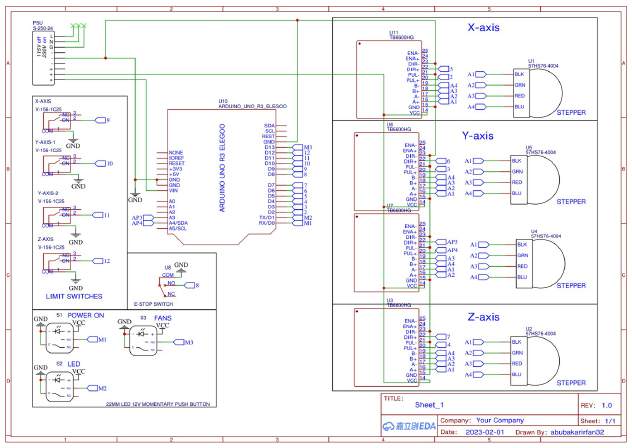
A wiring package for a CNC controller, covering motor interfaces and limit or safety input connections.
Project design or interface view — CNC controller wiring packageTechnical notes and images
Motion connections
The drawing groups motor connections by axis. X and Z have their own sections, while the Y-axis section contains two stepper connections, making the machine’s motion wiring easier to follow.
Machine inputs
Limit switches and an emergency-stop connection are shown alongside the controller. Their placement in the same package makes these inputs part of the overall wiring discussion, rather than a separate installation note.
Assembly reference
Power, ground and control connections share the same drawing. For assembly and troubleshooting, the useful detail is the ability to trace a connection from the controller to the relevant driver, motor or input.
Record 088 / Hardware and PCB
Multi sheet embedded schematic design
Schematic design
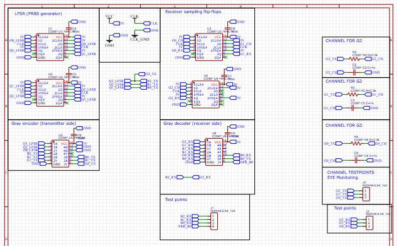
A multi sheet schematic package organising embedded interfaces and power domains.
Project design or interface view — Multi sheet embedded schematic designTechnical notes and images
Functional grouping
The schematic labels the transmitter-side generator and Gray encoder separately from the receiver sampling and decoder. These groups give the reader an entry point into the circuit’s signal flow.
Named-net connections
Named nets connect the logic groups with channel sections. Keeping those relationships visible matters when a signal passes through several functional blocks before returning to a decoded output.
Test and monitoring points
The drawing includes test-point groups and channel monitoring connections. Their presence makes intended observation locations part of the design documentation, alongside the circuit connections themselves.
Record 098 / Hardware and PCB
Compact Class D amplifier PCB
Design and layout refinement
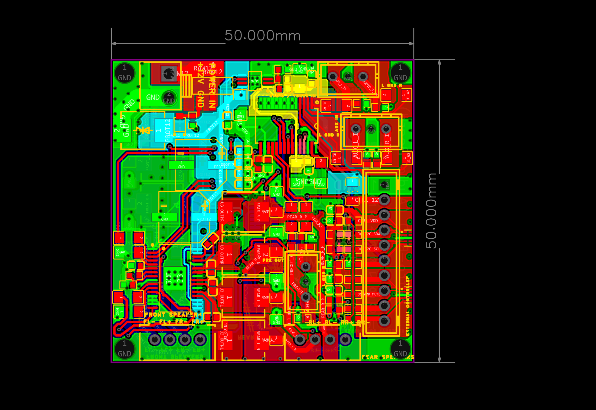
A restored car radio needs modern amplifier electronics within a fixed board outline. The design brings audio inputs, front and rear speaker connections, control signals and a vehicle supply into a 50 × 50 mm footprint.
Class D audioPCB layoutPower routingGroundingAutomotive supply
PCB design view. Placement and routing are under review and refinement.Technical notes and images
Board outline and placement
The fixed board outline determines where the connectors, amplifier stages and supporting components can sit. Power enters near one corner, while the audio and speaker connections occupy the board edges. Placement has to make those connections practical within the existing radio assembly.
Power and audio layout
The design review covers component choice, supply protection, local decoupling and the return paths around the amplifier stages. Copper areas, track routing and via placement are considered together because the board carries both switched power and audio signals in a small space.
Layout review
The three views expose different parts of the same board: component placement, routing and copper coverage. The design is being refined through schematic, component and layout review.
Firmware and control / 33 records
Record 002 / Firmware and control
Arduino Nano MIDI control interface
Firmware development
A MIDI control interface using an Arduino Nano and physical controls. The work covers control input handling and MIDI event generation.
Arduino NanoMIDIPhysical controls
Technical notes and images
Keypad and encoder input
Keypad input identifies a selected key; encoder input supplies an increment or decrement. Both are processed before a MIDI event is generated.
Scaling and debouncing
Scaling maps control values to the intended MIDI range. Debouncing prevents contact chatter from becoming repeated actions.
MIDI event generation
MIDI event generation is separate from physical input processing, allowing the control arrangement and event formatting to be handled independently.
Record 003 / Firmware and control
Embedded audio playback controller
Firmware development
Audio playback control built around a Teensy, with peripheral interfaces and storage integration.
TeensyI2CSPISD storage
Technical notes and images
Playback state
Playback control uses an operating state to distinguish new commands, repeated inputs and actions that are not currently relevant.
Peripheral connections
The controller work spans I2C, SPI and UART peripheral connections, with each interface linked to its component or communication path.
Storage alongside control
Storage integration and SD-related logging are handled separately from playback commands and local user control.
Record 004 / Firmware and control
LVGL display configuration package
Software configuration
Configuration work for an embedded display interface using LVGL. Scope includes display setup and application interface organisation.
LVGLEmbedded display
Technical notes and images
Display configuration
Configuration connects the graphics library with the display and input paths before application screens are developed.
Touch and application state
Touch events need an application meaning, such as choosing a screen or changing a setting. Organising those responsibilities helps prevent display setup from becoming mixed with application logic.
Graphics and communication interfaces
The package spans LVGL graphics, SPI peripherals and HTTP or REST interfaces within the embedded application.
Record 007 / Firmware and control
Configurable stepper motion script
Firmware development
Configurable stepper movement with control of motion timing and direction.
Stepper controlMotion timing
Technical notes and images
Motion timing and direction
Timing controls the rate of commanded steps; direction controls their sense. Both are configurable motion settings.
Stepper driver interface
The script controls the stepper driver, which provides the electrical interface to the motor.
Motion sequence definition
A repeatable command needs a clear start, progression and end. These are useful review points for configurable motion, before considering mechanical loading and motor response.
Record 009 / Firmware and control
MIDI joystick and fader bank
Firmware development
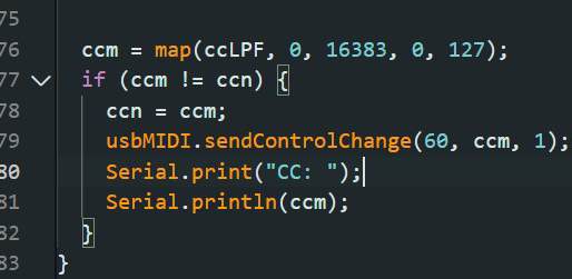
MIDI control input processing for a joystick and faders. Moving average and low pass filtering routines support signal conditioning.
MIDIAnalog controlsSignal filtering
Project design or interface view — MIDI joystick and fader bankTechnical notes and images
Input filtering
applyMovingAverage() and applyLowPassFilter() condition input data using different forms of smoothing.
Smoothing and response
Smoothing and response must be considered together. A value that barely moves may look stable but feel slow, while an unfiltered input may send unwanted changes.
MIDI event generation
Conditioned input values are converted to MIDI events, with input processing kept separate from event generation.
Record 010 / Firmware and control
Motorised FM radio sweep controller
Firmware development
Control logic for a motorised FM radio sweep system, including button input and sweep speed adjustment.
Motor controlFM radioInput handling
Technical notes and images
Button input
handleButtons() processes local button input before it changes the sweep.
Sweep speed control
adjustSweepSpeed() handles the sweep-speed setting within the motor control firmware.
LCD feedback
updateLCD() handles local display updates so the operator can see the setting being adjusted.
Record 012 / Firmware and control
Fingerprint and keypad access controller
Firmware development
An access control interface combining fingerprint input, keypad entry and local feedback.
Fingerprint interfaceKeypadAccess logic
Firmware flow
How a released keypad key is handled
Selected keypad input and backspace branch.
CheckIs a key pressed?Read the keypad and show the password prompt.
A press is remembered. After release, a valid key is mapped and the timeout restarts. In the shown backspace branch, the final character is removed only when the input is not empty.
This is only part of the password-entry routine. It does not show password comparison, fingerprint verification or door control.
Read the implementation
getPasswordFromKeypad excerpt · selected source lines 110–130. Source inspection is not a hardware test.
    uint8_t currentKey = keypad.getKey();
    lcd.setCursor(0, 0);
    lcd.print("Enter Password:");

    if (currentKey != I2C_KEYPAD_NOKEY) {
      lastKey = currentKey;
      wasPressed = true;
    } else if (wasPressed) {
      wasPressed = false;

      if (lastKey < 16) {
        char key = keymap[lastKey];
        startTime = millis(); // 🔄 Reset timeout on key press

        switch (key) {
          case 'D':  // Backspace
            if (inputBuffer.length() > 0) {
              inputBuffer.remove(inputBuffer.length() - 1);
              Serial.println("Deleted last character");
            }
            break;
stepperMove() handles motion separately from input parsing.
Local status feedback
The local display and serial interfaces provide feedback during device interaction.
Record 013 / Firmware and control
Encoder referenced stepper controller
Firmware development
Stepper control using an encoder reference to relate commanded movement to position input.
Stepper controlEncoder input
Technical notes and images
Command and position input
The controller relates movement commands to position information from the encoder.
Step generation
generateSteps() handles step generation separately from command and reference interpretation.
Communication and driver interfaces
UART communication, stepper control and the motor driver form distinct interfaces in the movement-control path.
Record 019 / Firmware and control
RTC timed motor and servo controller
Firmware development
Motor and servo operations scheduled using a real time clock.
RTCMotor controlServo control
Project design or interface view — RTC timed motor and servo controllerTechnical notes and images
Scheduling and actuation timing
A scheduled event answers when an action should begin. Motor control answers what happens during that action. Keeping those decisions separate makes the overall sequence easier to follow.
Motor start and stop
moveMotor() and stopMotor() define the start and end of a motor action.
Peripheral integration
The controller brings together servo control, motor drive, I2C and UART. Their integration supports scheduled operation without requiring the clock interface to contain the actuation logic.
Record 020 / Firmware and control
Fingerprint enrolment and verification firmware
Firmware development
Firmware for enrolling fingerprints and checking subsequent reads against stored records.
Fingerprint interfaceEnrolmentVerification logic
Firmware flow
How a fingerprint is checked
Fingerprint verification routine.
ActionWait for a fingerprint imageRequest another image every 50 ms until acquisition succeeds.
Wait for an image, convert it to a fingerprint template and search stored records. A conversion error stops the routine; the search reports either a matching ID and confidence or a no-match error.
The function waits for an image without a timeout in the supplied code. It reports search results, not an independently measured recognition rate.
Read the implementation
verifyReload · selected source lines 260–280. Source inspection is not a hardware test.
void verifyReload() {
  Serial.println(F("❓ Verify: place the same finger…"));
  // 1) wait for finger
  while (finger.getImage() != FINGERPRINT_OK) delay(50);
  if (finger.image2Tz(1) != FINGERPRINT_OK) {
    Serial.println(F("⚠️ image2Tz fail"));
    return;
  }
  // 2) search the buffer 1 template against slot 1
  uint8_t res = finger.fingerFastSearch();
  if (res == FINGERPRINT_OK) {
    Serial.print(F("✅ Match! ID="));
    Serial.print(finger.fingerID);
    Serial.print(F("  Confidence="));
    Serial.println(finger.confidence);
  } else {
    Serial.print(F("❌ No match (err 0x"));
    Serial.print(res, HEX);
    Serial.println(F(")"));
  }
}
sensorSerialBegin() provides a communication setup step separate from fingerprint enrolment and verification. This keeps transport handling identifiable.
Fingerprint enrolment
enrollFingerprint() handles registration separately from later fingerprint checks.
Stored model handling
downloadModelToString() and reloadFingerprint() handle model representation and reloading separately from matching a presented fingerprint.
Record 021 / Firmware and control
Text to Braille and speech controller
Development work
An embedded interface coordinating text input with tactile and spoken output.
Braille interfaceSpeech outputPeripheral control
Technical notes and images
Letters, words and lines
sayLetter(), sayKnownWord() and speakLine() distinguish character, word and line operations. The separate routines make each level of speech output explicit in the implementation.
Shift-register output
pushToShiftRegs() sends tactile output through shift registers, separately from text interpretation.
Shared input, separate outputs
BLE, SPI and USB interface work supports the coordination of text processing with spoken and tactile output.
Record 024 / Firmware and control
Wearable motion firmware
Firmware development
Motion triggered wearable firmware with lighting control and sleep or wake routines. The source includes vibration wake handling.
Motion inputLow power firmwareLighting control
Technical notes and images
Lighting control
applyColor() and ledsOff() define the active lighting effect and the inactive output.
Vibration wake-up
enableVibrationPCINT() and enterPowerDownUntilVibration() define the vibration-based wake path and the event that resumes operation.
Sleep and wake sequence
Going idle and returning to active operation are connected decisions. The firmware work addresses that transition, while actual battery life still depends on the complete hardware and its measured consumption.
Record 026 / Firmware and control
Encoder based BLE motor controller
Firmware development
A motor controller combining BLE commands with encoder based input or feedback.
BLEEncoder inputMotor control
Technical notes and images
BLE commands and encoder input
BLE commands and encoder events provide distinct inputs to the motor application.
Encoder handling
An encoder interrupt routine captures events alongside communication and motor control.
Command and motion processing
The firmware integrates the wireless command path, encoder events and motor output handling.
Record 027 / Firmware and control
Relay sequencing controller
Firmware development
Control logic for sequencing relay outputs according to defined operating states.
Relay controlSequencingEmbedded firmware
Technical notes and images
Relay sequence states
Operating states define where each relay output belongs in the switching sequence.
Embedded output control
The firmware scope combines relay or solenoid control, I2C interfaces and embedded C/C++.
State transitions
The sequence identifies the active state, its associated output and the condition for the next transition.
Record 028 / Firmware and control
ESP32 audio and motor controller
Firmware development
An ESP32 control application combining audio playback and motor outputs.
ESP32Audio controlMotor control
Project design or interface view — ESP32 audio and motor controllerTechnical notes and images
Serial playback commands
A dedicated routine sends MP3 playback commands.
Coordinated audio and motion
Motor actions and audio playback are part of the same control application.
Separate output interfaces
Serial playback and motor control retain separate output handling within the application.
Record 045 / Firmware and control
Themed prop smoke motor and LED controller
Firmware development
Control work coordinating smoke, motor and LED outputs in a themed prop.
Motor controlLED controlOutput sequencing
Project design or interface view — Themed prop smoke motor and LED controllerTechnical notes and images
Coordinated prop outputs
The application coordinates motor control, addressable lighting and a smoke relay.
Explicit output handling
Routines handle button presses, active-high output configuration, smoke-relay writes and LED indexing.
LED and relay interfaces
LED updates and relay commands have separate handling within the prop’s output sequence.
Record 046 / Firmware and control
Motion triggered light and sound prop
Firmware development
Motion input used to trigger coordinated lighting and sound output.
Motion inputLightingAudio control
Technical notes and images
Tilt-trigger handling
A tilt-trigger routine converts movement into an event for the effect logic.
Lighting actions
Routines show blue, turn outputs off and fade a white element. These lighting actions can form part of the prop's response to movement.
Coordinated feedback
Motion input coordinates lighting and sound within the same application.
Record 056 / Firmware and control
LUFA USB descriptor package
Firmware module
USB descriptor configuration and callback handling for a LUFA based device.
LUFAUSB descriptorsEmbedded C
Technical notes and images
USB device descriptors
USB descriptors identify the device and its interfaces to the host.
Descriptor callback
CALLBACK_USB_GetDescriptor() handles host descriptor requests in the LUFA firmware.
Descriptor package
The package defines descriptor data and request handling for the intended USB interface.
Record 057 / Firmware and control
ESP32 Bluetooth keyboard controller
Firmware development
An ESP32 application implementing a Bluetooth keyboard control interface.
ESP32BLEKeyboard interface
Firmware flow
How a joystick creates left and right key presses
Selected horizontal-axis Bluetooth keyboard handling.
ResultWait briefly, then release the keysThe shown delay is 150 ms.
When Bluetooth is connected, read the joystick and ignore small horizontal movement. A larger movement sends the matching arrow key, waits 150 ms and releases the keys.
The snippet reads both axes but only shows horizontal key handling. It does not establish behaviour after disconnection or the complete keyboard mapping.
Read the implementation
loop excerpt · selected source lines 40–58. Source inspection is not a hardware test.
void loop() {
  // Ensure BLE keyboard is connected
  if (bleKeyboard.isConnected()) {
    // Read joystick values
    int joystickX = analogRead(JOYSTICK_X) - 2048; // Adjust for ESP32 ADC range
    int joystickY = analogRead(JOYSTICK_Y) - 2048;

    // Handle joystick movements
    if (abs(joystickX) > DEADZONE) {
      if (joystickX > 0) {
        bleKeyboard.press(KEY_RIGHT_ARROW); // Joystick moved RIGHT
        Serial.println("Joystick RIGHT");
      } else {
        bleKeyboard.press(KEY_LEFT_ARROW); // Joystick moved LEFT
        Serial.println("Joystick LEFT");
      }
      delay(150);
      bleKeyboard.releaseAll(); // Release after press
    }
The firmware translates local control actions into keyboard input for the host.
BLE host connection
BLE carries keyboard input between the ESP32 and its host.
Keyboard interface scope
The module provides an embedded keyboard interface for custom controls used with applications that accept keyboard input.
Record 058 / Firmware and control
IMU assisted motor and servo controller
Firmware development
Control logic combining IMU input with motor and servo outputs.
IMUMotor controlServo control
Technical notes and images
Sensing and actuation
The control scope relates IMU motion or orientation readings to actuator commands.
Motor and servo outputs
Motor drive and servo control have separate output handling within the application.
Motion-to-command mapping
The control decision translates sensed motion or orientation into a movement command. Keeping this step distinct clarifies the relationship between the sensor and each actuator during development.
Record 060 / Firmware and control
ESP-01S wireless smoke and LED controller
Firmware development
One remote button selects lighting actions by press duration. An ESP-NOW receiver keeps the colour and effect state locally.
Result · NoClear the local payload; remember input state
On a LOW-to-HIGH release, select a command from the duration bands and send it over ESP-NOW. A release in the 2500–2999 ms gap sends no command. Afterwards clear the payload locally and remember the input state.
A release lasting 2500–2999 ms matches no command. The zero reset is local and is not transmitted. No receiver failsafe, delivery acknowledgement or hardware retest is established.
Read the implementation
loop() selected body · selected source lines 67–94. Source inspection is not a hardware test.
Result · No matchClear the selector; remember input state
Choose the first matching local or remote command. It may initialise the LEDs and change colour, call the strobe routine, change the effect flags or lower the output pin. Clear the remote selector after the branch.
The receiver snapshot is incomplete for standalone compilation. Local release conditions can take precedence over remote selectors because this is a first-match chain. No link-loss failsafe or tested output behaviour is established.
Read the implementation
loop() selected body · selected source lines 95–131. Source inspection is not a hardware test.
  if ((newState == HIGH) && (oldState == LOW) && (millis() - lowSignalStartTime < 500) || sel == 1) {  // FIXME: color change delay
    if (!ledInitialized) {
        for(int i=0; i<=NUM_LEDS; i++){
  strip.setPixelColor(i, strip.gamma32(strip.ColorHSV(huewa, 255, 255)));  // Set initial color
      strip.begin();
      strip.show();}
      digitalWrite(1, HIGH);
      ledInitialized = true;  // Set the flag to true
    }
    modeChange();  // Color Transition

  } else if ((newState == HIGH) && (oldState == LOW) && (millis() - lowSignalStartTime >= 650) || sel == 2) {  // FIXME: strobe effect trigger delay

    beameffect();  // Trigger Strobe Effect

  } else if (sel == 3) {

    flash = true;           // layermode
    glittereffect = false;  // glitter mode

  } else if (sel == 4) {

    glittereffect = true;
    flash = false;

  } else if (sel == 5) {

    glittereffect = false;  //all off
    flash = false;

  } else if (sel == 6) {
    digitalWrite(1, LOW);
  }

  // Set the last-read button state to the old state.
  sel = 0;
  oldState = newState;
The sender measures a button hold and sends one command when the button returns HIGH. The receiver keeps the effect state locally, so a packet selects an action rather than carrying every LED update.
Duration bands and their boundary
The sender assigns commands 1–5 to successive ranges below 2500 ms, then command 6 at 3000 ms or more. The inspected version has no send branch for 2500–2999 ms. After the branch chain it clears the local payload, without transmitting a reset packet.
Receiver command dispatch
The first-match chain combines local button conditions with remote selectors. It can initialize the strip and raise GPIO1, advance the hue mode, call the strobe routine, switch flash/glitter flags, or lower GPIO1. Command 5 clears two effect flags; it is not an all-output shutdown. Command 6 lowers GPIO1 without clearing the LED initialization flag.
Scope of the source evidence
The transmitter includes ESP8266WiFi.h and both files use the ESP8266-era ESP-NOW API, correcting the old ESP32 label. The receiver snapshot omits declarations needed to compile it alone. No link-loss timeout or fail-safe is established by these files, and no hardware retest is claimed.
Record 063 / Firmware and control
Deterministic motor step sequence
Firmware module
Motor movement arranged as an explicit sequence of timed steps.
For each requested step, raise the step pin, wait for the pulse interval, lower it and wait for the configured low interval. Repeat until the requested count is reached.
There is no acceleration profile, position feedback or measured timing guarantee in this excerpt. The high-pulse delay and low-period delay are separate, so the total cycle includes both.
Read the implementation
stepMove pulse-loop excerpt · selected source lines 36–42. Source inspection is not a hardware test.
  for (long i = 0; i < steps; i++) {
    digitalWrite(STEP_PIN, HIGH);
    delayMicroseconds(STEP_PULSE_US);
    digitalWrite(STEP_PIN, LOW);
    // Keep overall step rate controlled:
    delayMicroseconds(STEP_PERIOD_US);
  }
Relay and motor control firmware with current measurement input.
Current monitoringRelay controlMotor control
Technical notes and images
Commands and current readings
Relay and motor commands describe what the controller asks the hardware to do. Current information describes another aspect of the system, helping distinguish an output request from the load's electrical state.
Local input handling
updateButtons() handles local input alongside switched outputs and current measurement.
Control and measurement integration
The firmware integrates operator input, motor control, relay operation and current measurement.
Record 068 / Firmware and control
IMU stabilised stepper platform
Development work
A stepper platform control application using IMU feedback.
Read the current angle, subtract it from the target, scale the error using the step settings and pass that value to the stepper speed function.
The computed value is passed to a speed setter, not to a position-move command. The excerpt does not establish closed-loop stability, tuning or a tested accuracy.
Read the implementation
stabilizeMotor · selected source lines 149–155. Source inspection is not a hardware test.
moveLeft() and moveRight() provide explicit direction-control operations.
Sweep mode
toggleSweep() and sweepMotor() distinguish selecting a sweep mode from executing it. That separation gives a movement pattern its own ongoing state.
IMU feedback
The development work connects IMU orientation feedback with the stepper platform’s movement commands.
Record 069 / Firmware and control
ESP32 motor and power stage controller
Firmware development
ESP32 firmware for motor commands and power stage control.
ESP32Motor controlPower stage interface
Technical notes and images
Power and control connections
The power stage reference distinguishes motor phase and supply connections from its low voltage control connections. That separation explains where the ESP32's firmware responsibilities meet the power hardware.
Driver control signals
The driver reference identifies speed, direction, brake and stop connections.
Firmware integration
ESP32 firmware handles motor and power-stage commands through the connections defined by the driver reference.
Record 074 / Firmware and control
Sequenced multi servo controller
Firmware development
Firmware for running a defined sequence across multiple servo outputs.
Servo controlSequencingUART
Technical notes and images
Servo sequence routine
runServoSequence() provides the entry point for the coordinated servo movement.
Coordinated servo timing
A multi-servo sequence depends on the timing of each action relative to the others. A defined sequence records those relationships in the program.
UART integration
UART communication is integrated with the control application, separately from the servo sequence routine.
Record 075 / Firmware and control
Embedded control firmware module
Firmware module
An embedded control module covering device states and hardware interfacing.
Embedded C++State controlHardware interfaces
Technical notes and images
State-based control
Embedded C++ state-based control relates the current device state to its hardware-facing actions.
Hardware interfaces
The module covers input handling, control decisions and hardware outputs.
Firmware scope
The central task is translating the device's intended operation into explicit firmware responsibilities at the hardware interface.
Record 076 / Firmware and control
Keypad based multi zone alarm
Firmware development
Alarm logic with keypad entry, PIN checking and multiple monitored zones.
KeypadPIN checkingAlarm logicLocal display
Technical notes and images
Keypad and zone inputs
Keypad entry and monitored zones provide different inputs to the alarm logic, with PIN verification handled separately.
PIN handling
checkPincode() and comparePincode() handle credential checks separately from zone monitoring.
Local feedback
A local display shows feedback on entered commands and the alarm’s current condition.
Record 078 / Firmware and control
PCA9685 multi channel servo interface
Firmware module
A multi channel servo interface built around the PCA9685 driver.
PCA9685Servo controlI2C
Project design or interface view — PCA9685 multi channel servo interfaceTechnical notes and images
Channel organisation
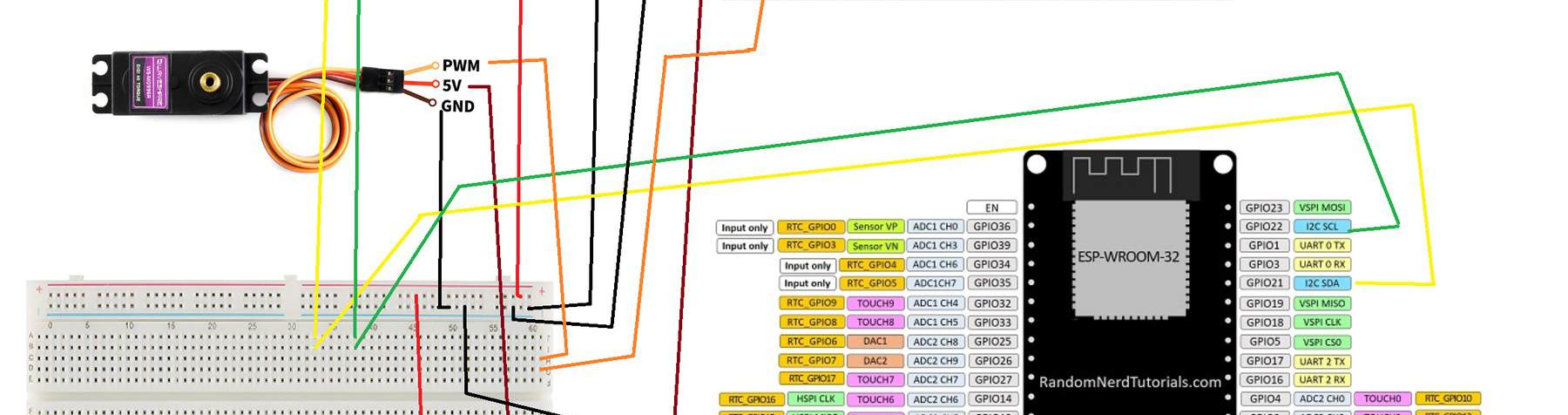
The PCA9685 forms the centre of the servo interface. A shared control connection lets the firmware address multiple outputs through a dedicated driver rather than treating each servo as a separate software interface.
Physical connections
The wiring illustration identifies the servo's signal, supply and ground connections beside an ESP32 pinout. This connects the software-facing interface to the wiring required at the actuator.
Command and power interfaces
Servo command handling and actuator power are related but separate concerns. Wiring documentation makes that distinction clear before assessing movement on the bench.
Record 081 / Firmware and control
BLE relay control firmware
Firmware module
Relay output control through a BLE interface.
BLERelay controlEmbedded firmware
Technical notes and images
BLE commands
BLE commands provide the input to the relay-control module.
Command-to-relay mapping
Firmware links received commands to relay output handling; the control scope also includes an interrupt routine.
Output switching
Relay control converts the requested software state into a physical switching action.
Record 084 / Firmware and control
ESP32 BLE game controller interface
Firmware development
An ESP32 BLE interface translating physical input into game controller actions, with timed button press and release handling.
The press helper sends one button press and records its start time when the button is not already held. A separately called release helper releases it once the configured hold time has elapsed.
The caller decides when each helper runs. This overview does not imply a blocking wait or prove the complete input mapping.
Read the implementation
press/release functions · selected source lines 94–107. Source inspection is not a hardware test.
setupEncoder() handles physical input for translation into game-controller actions.
Button activation
tapButtonIfNeeded() handles button activation, with timing separate from the duration of the physical input.
Timed release
releaseIfElapsed() handles timed release to complete a button tap over the BLE interface.
Record 089 / Firmware and control
Accident alert greenhouse and BLDC control set
Firmware collection
A collection of embedded control work covering an accident alert interface, greenhouse functions and BLDC control.
ESP32Alert logicEnvironmental controlBLDC control
Technical notes and images
Accident-alert interface
The alert work includes button handling, output control, buzzer pulses and LED indication. Named routines such as debouncedPressed() and setAlertOutputs() identify those parts of the interaction.
Greenhouse functions
Environmental control forms another part of the collection. Its engineering emphasis is the relationship between conditions being monitored and the control actions associated with them.
BLDC control
Motor control introduces a different output responsibility. Bringing it into the collection shows the range from discrete alert feedback to firmware concerned with controlling a motor interface.
Record 096 / Firmware and control
N64 stick calibration firmware
Delivered firmware / follow-up refinement
ATtiny84A firmware calibrates a replacement joystick for an N64 stick converter. The centre position and eight directional references define the usable travel and its mapping to the console’s expected output.
Read the referencesUse the centre and eight directional positions.
Map the stick travelRelate movement to the expected output coordinates.
Review the outputCompare captured signals with applied movements.
Check calibration retentionTest console reset and power cycling separately.
Technical notes and images
Calibration fault
The reported failure appeared after calibration: stick movement could produce zero output on both axes. The work focused on how calibration readings became usable coordinates, including the relationship between the neutral position and the outer reference points.
Signal verification
The firmware was revised and tested using captured output and practical stick movements. Logic analyser checks helped relate what the converter transmitted to the direction and position being applied. The corrected firmware was delivered with the project files.
Reset and power-cycle testing
Follow-up testing raised a different issue: the client reported that the console reset button affected calibration even though a full power cycle did not. The ongoing work checks calibration storage and startup behaviour across those two events.
Connected systems / 24 records
Record 017 / Connected systems
NFC inventory interface
Firmware module
A low level NFC interface with byte exchange and diagnostic output routines for tag communication.
NFCProtocol handlingDiagnostics
Technical notes and images
Sending and receiving frames
sendFrame() and readFrame() handle outgoing requests and incoming data.
Waiting for a byte
readByteWait() handles byte reception separately from interpretation of a complete tag response.
Hexadecimal diagnostics
dumpHex() exposes the exchanged data in hexadecimal form for protocol inspection.
Record 023 / Connected systems
NFC tag and web workflow prototype
Prototype development
An NFC terminal linked to a web workflow. Project material covers tag operations and device or browser status handling.
Split the payload into four-byte pages, stopping if a payload-page write fails. Pause between pages. Once all payload bytes are written, write a zero-filled page and return success without checking that final write.
Payload-page failures are checked, but the final zero-filled page write is not checked before success is returned. This does not verify the browser workflow or a successful physical tag write.
Read the implementation
writePagesPaced · selected source lines 69–82. Source inspection is not a hardware test.
The NFC or PN532-related interface handles physical tag operations at the terminal.
Device and browser status
Device and browser status handling connects local tag operations with the information shown in the web interface.
Terminal and web responsibilities
The terminal provides the physical tag interaction; the web workflow supplies its application context.
Record 025 / Connected systems
ESP32 C3 lap timer and servo gate
Prototype development
Provide a local browser interface to release a toy car and measure its lap time.
ESP32 C3Wi Fi access pointBrowser interfaceServo controlLaser sensing
Technical notes and images
Local Wi-Fi connection
The controller creates its own Wi Fi access point. The browser portal therefore works without an external router, keeping the control interface close to the track and reducing setup dependencies.
Browser command and servo gate
A portal command releases the servo gate. Lap timing and laser detection connect that physical action to a recorded result, bringing movement, sensing and browser interaction into one prototype.
Laser lap timing
The useful distinction is between the user command and the sensor event. The sensor supplies the finish event rather than relying on a person to stop the timer, connecting a physical crossing to the lap result.
Record 032 / Connected systems
ESP32 Modbus and RS485 data logger
Development work
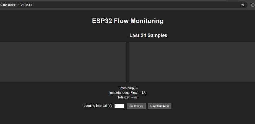
Read field instrument values over a wired industrial interface and make them available through a connected logger.
ESP32ModbusRS485Wi FiData logging
Project design or interface view — ESP32 Modbus and RS485 data logger
Firmware flow
How instrument registers become useful readings
Selected Modbus flow-rate and accumulator readers.
Each reader requests its registers, returns an unavailable value on communication failure, and otherwise decodes the words into either instantaneous flow or an accumulated reading.
The two readers are separate functions, not a guaranteed call sequence. Register layout and hardware multiplier settings are assumed by the code; no instrument validation is shown.
Read the implementation
regToFloat / readFlowRate / readPositiveAccum · selected source lines 31–52. Source inspection is not a hardware test.
float regToFloat(uint16_t hi, uint16_t lo) {
  union { uint32_t U; float F; } u;
  u.U = ((uint32_t)hi << 16) | lo;
  return u.F;
}
// Read instantaneous flow (m³/h), then convert to L/s
float readFlowRate() {
  if (node.readHoldingRegisters(0x0000, 2) != node.ku8MBSuccess) return NAN;
  return regToFloat(node.getResponseBuffer(0), node.getResponseBuffer(1)) * 0.2778;
}

// Read positive accumulator (LONG + fraction)
float readPositiveAccum() {
  // INTEGER part at reg 0009 -> offset 8, fraction at 0011 -> offset 10
  if (node.readHoldingRegisters(0x0008, 4) != node.ku8MBSuccess) return NAN;
  // lower two regs = integer, upper two = fraction
  int32_t N  = (int32_t)node.getResponseBuffer(0) << 16
             | node.getResponseBuffer(1);
  float   Nf = regToFloat(node.getResponseBuffer(2), node.getResponseBuffer(3));
  // multiplier n is handled in hardware (M33/M31), so assume direct (no extra 10ⁿ)
  return N + Nf;
}
Separate routines read flow rate and positive accumulation. Register conversion translates the raw device response into application values.
Connected reporting
Wi Fi, WebSocket updates and a broadcast routine connect the instrument-facing code to the viewing interface.
Flow rate and accumulation
Flow rate describes current activity; accumulated values describe a total. Both pass through the logger with their meanings kept distinct.
Record 034 / Connected systems
ESP32 to Teensy LED bridge
Firmware module
An interface between an ESP32 and a Teensy for exchanging LED control information.
ESP32TeensyLED control
Technical notes and images
Controller communication
The two controllers exchange LED control information through a defined communication interface.
I2C request handling
I2C communication and a request-event routine handle information requests between the controllers.
LED bridge integration
The bridge handles controller-to-controller communication separately from the lighting effects that use its commands.
Record 035 / Connected systems
Bluetooth environmental sensor link
Development work
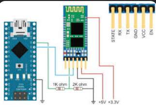
A DHT11 sensor supplies temperature and humidity readings to a Bluetooth serial link. The firmware checks the measurements before formatting them for an HC-05 receiver.
ResultSend over Bluetooth serialAlso print the packet to the local serial log.
Read temperature and humidity. If either reading is invalid, send a sensor-read error and stop. Otherwise format the values and send them through the HC-05 serial interface.
This establishes the packet-building logic, not wireless range, delivery confirmation or sensor accuracy.
Read the implementation
sendDHT11Data · selected source lines 187–206. Source inspection is not a hardware test.
HC05 configuration and AT command routines set up the communication module.
Sensor transmission
A DHT11 reporting routine connects sensor acquisition with transmission through the Bluetooth interface.
Configuration and data
Configuration commands and sensor readings have separate roles on the serial path.
Record 039 / Connected systems
ESP32 and FRDM I2C interface pair
Firmware module
I2C communication work connecting ESP32 and FRDM development platforms.
ESP32FRDMI2C
Technical notes and images
I2C platform connection
The two platforms exchange information over a shared bus, with platform-specific firmware on each side.
Receiving bus events
An I2C slave callback handles incoming bus events within the interface module.
Communication module scope
The work is a communication module, not a complete product. It connects bus activity with the firmware that handles it.
Record 040 / Connected systems
Pool monitoring and web diagnostics node
Development work
A pool monitoring interface with device data retrieval and web diagnostics. The documented routines include response parsing and sampling sequence checks.
ESP32Web diagnosticsData acquisition
Technical notes and images
Response parsing
Data-request and response-reading routines parse information from the monitored device.
Sampling sequence
Cuvette-fill checks and a pause after refilling relate sampling readiness to measurement handling.
Web diagnostics
Web diagnostics expose the communication and sampling process for inspection during development.
Record 044 / Connected systems
ESP32 camera and calculator image interface
Development work
An ESP32 camera workflow for moving image data into a calculator related interface.
ESP32CameraImage transferInterface integration
Project design or interface view — ESP32 camera and calculator image interfaceTechnical notes and images
Image capture and transfer
Capturing an image is only one part of an interface task. The receiving environment also needs usable data and a defined way to start an operation and recognise whether it succeeded.
Command and result handling
Command initiation, string handling and success or error states support the ESP32 image-transfer workflow over Wi Fi and HTTP.
Transfer status
Success and error states distinguish a completed transfer from an operation needing attention.
Record 047 / Connected systems
GNSS and LoRa race tracker
System development
Firmware and a browser interface for a radio-based race-tracking system. The work covers position and status packets, a LoRa-to-web gateway, map updates and GPX route logging.
Check that position and satellite data are valid with at least one satellite. Keep the coordinates when a fix is available; otherwise mark no fix and use zero placeholders. Add independently valid auxiliary readings, then update the latest fix, quality and satellite status.
The check is for reported field validity, not sample freshness or an accuracy threshold. Zero coordinates are placeholders when there is no fix. LoRa transmission, browser maps and GPX logging are outside this excerpt.
Read the implementation
buildGpsSample · selected source lines 1040–1053. Source inspection is not a hardware test.
The telemetry format carries position and status in compact packets. This gives the radio link a defined data representation rather than coupling the map directly to the GNSS device.
Radio-to-web gateway
Gateway software bridges the radio side to WebSocket updates. That boundary connects the embedded communication path to browser software while keeping the radio packet and user interface responsibilities distinct.
Map and route record
Browser map development turns position information into a spatial view, while GPX logging provides a route record. Together they connect the incoming telemetry with two useful ways of examining a race tracking system.
Record 048 / Connected systems
Dual board hydrogen controller interface
Development work
An ESP32 and CAN interface for a controller split across two boards, including output setup and PWM handling.
ESP32CANPWMBoard interfaces
Technical notes and images
Two-board architecture
CAN links the distributed control functions across two boards; local firmware handles each board’s outputs.
PWM pin mapping
Routines assign PWM to pins, write PWM values, find the channel associated with a pin and set up outputs. These give the firmware a defined mapping between application outputs and hardware resources.
Communication and actuation
A command crossing the board boundary is different from a local PWM update. Keeping these responsibilities explicit helps the controller relate distributed communication to the output work performed on each board.
Record 051 / Connected systems
Cloud connected pump and reagent controller
Development work
Pump and reagent control linked to a cloud interface, with output state handling and publication or retry logic.
Pump controlWi FiCloud integrationOutput control
Project design or interface view — Cloud connected pump and reagent controllerTechnical notes and images
Pump and output control
A pump routine controls the output, while allOutputsOff() returns the outputs to an inactive state.
Publication and queue handling
safePublish() and tryOrQueue() handle cloud publication and information waiting to be sent.
Output and network state
The scope covers both physical output state and the progress of network publication.
Project design or interface view — Cloud connected pump and reagent controller
Record 052 / Connected systems
MQTT IMU and cellular telemetry node
Development work
A telemetry node combining motion sensor information with MQTT and cellular communication.
MQTTIMUCellular telemetryESP32
Technical notes and images
IMU acquisition
setupMPU() initialises the IMU before its motion readings are used by the application.
Network setup
Wi Fi station setup and routines such as sendHeader() and waitFor() handle connection preparation.
MQTT telemetry
MQTT supplies remote reporting for the motion-sensor application.
Record 055 / Connected systems
Art Net UDP lighting interface
Firmware module
A lighting interface using Art Net and UDP communication.
Art NetUDPLighting control
Firmware flow
How lighting data becomes an LED frame
Selected Art-Net frame handling code.
ActionCheck the tracked lighting packetsA missing universe clears the frame-ready flag.
Result · YesDisplay the frame and clear packet tracking
Result · NoKeep the buffered values without displaying
Check packet tracking, place the RGB values into the LED buffer and update the remembered packet length. Display the frame and reset tracking only when the frame-ready flag is set.
The excerpt begins after earlier callback setup. It does not show how the frame-ready flag is initially set or how missing packets are recovered.
Read the implementation
onDmxFrame excerpt · selected source lines 72–94. Source inspection is not a hardware test.
  // Check that all universes have been received
  for (int i = 0; i < maxUniverses; i++) {
    if (!universesReceived[i]) {
      Serial.println("Something is broken...");
      sendFrame = false;
      break;
    }
  }

  // Map the DMX data to the appropriate LED(s) on the strip.
  for (int i = 0; i < length / 3; i++) {
    int led = i + (universe - startUniverse) * (previousDataLength / 3);
    if (led < numLeds)
      leds.setPixelColor(led, data[i * 3], data[i * 3 + 1], data[i * 3 + 2]);
  }
  previousDataLength = length;

  // Once all universes have been received, update the LED strip and reset the tracking array.
  if (sendFrame) {
    leds.show();
    memset(universesReceived, 0, sizeof(universesReceived));
  }
}
Art Net carries lighting data over UDP into the embedded application.
Network and output handling
Network reception and local lighting output are separate parts of the interface.
Protocol integration
The module connects incoming lighting-protocol data with the firmware that controls the output.
Record 061 / Connected systems
ESP32 embedded web monitor prototype
Prototype development
An ESP32 prototype exposing device information through an embedded web interface.
ESP32Embedded web interfaceMonitoring
Technical notes and images
Device status
The embedded web interface exposes local device information for inspection.
Firmware-to-browser interface
The project covers the relationship between local device operation and its web representation. This defines which information the browser can show and how it relates to the device.
Monitoring prototype
The prototype presents controller state through a browser-facing interface.
Record 071 / Connected systems
Wi Fi serial transport firmware
Firmware module
Firmware carrying serial data over a Wi Fi connection.
ESP32Wi FiUARTData transport
Technical notes and images
UART-to-Wi-Fi transport
UART-to-Wi-Fi transport connects the serial interface with the wireless data path.
Transmission completion
transmissionComplete() handles transfer completion within the firmware.
Wireless serial bridge
The module carries the surrounding device’s serial data over a wireless connection.
Record 072 / Connected systems
HAL to UDP motion interface
Firmware development
A motion interface linking hardware control functions to UDP communication, with PWM channel configuration and output updates.
ESP32UDPPWMHardware abstraction
Project design or interface view — HAL to UDP motion interface
Result · YesStore the timer mapping and return success
Result · NoReturn failure
Allocate a timer for the requested frequency, configure the selected channel with zero initial duty, then keep the timer-to-channel mapping. Return failure if no timer is available or configuration fails.
This is setup code for one output channel. It does not show UDP transport, real-time timing performance or motor behaviour.
Read the implementation
configure_pwm_channel excerpt · selected source lines 47–70. Source inspection is not a hardware test.
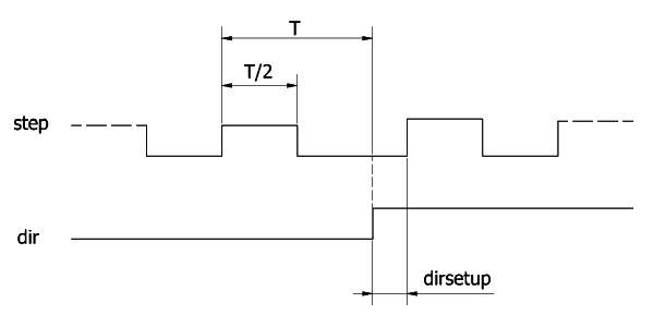
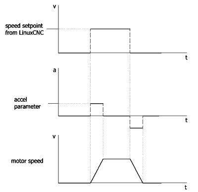
The reference drawings distinguish a LinuxCNC speed setpoint from the resulting motor speed, and show the relationship between step pulses and direction setup. These are different parts of the motion problem.
PWM configuration and updates
The firmware names configure_pwm_channel(), set_pwm_duty() and io_init(). This separates output preparation from later changes to the output value, making the hardware interface easier to follow.
UDP-to-hardware interface
UDP provides the communication side of the interface. The engineering work concerns how motion information reaches the hardware layer, without treating network message arrival as identical to a correctly timed motor signal.
Project design or interface view — HAL to UDP motion interface
Record 077 / Connected systems
ESP32 camera web server
Firmware development
An ESP32 camera interface providing image data through a web server.
ESP32CameraEmbedded web server
Technical notes and images
Camera-to-web interface
The system uses an ESP32 camera interface with an embedded web server. Wi-Fi provides the network connection between the camera device and the browser-facing service.
Image annotation routines
Image annotation routines include rgb_print(), rgb_printf() and draw_face_boxes(). They place image annotation alongside the camera serving portion of the firmware.
Embedded constraints
Image handling and network service share the same embedded device. That makes buffer use and the division of processing responsibilities relevant when developing a camera interface on this platform.
Record 079 / Connected systems
Triple channel CAN diagnostic interface
Development work
A diagnostic interface for reading and sending frames across three CAN channels.
CANBus diagnosticsFrame handling
Technical notes and images
Three bus contexts
The interface is organised around three CAN channels. Channel identity matters because the same frame identifier can have a different meaning on a different connected bus.
Frame handling
Named routines include sendMessage(), readBus() and readMsgFromBuffer(). Together they describe the core operations involved in moving frames between the diagnostic application and its bus interfaces.
Receive and transmit diagnostics
Receive and transmit functions distinguish observing CAN traffic from sending a frame onto the bus.
Record 083 / Connected systems
Cellular and Wi Fi MQTT gateway
Firmware development
A gateway linking local data with MQTT over cellular or Wi Fi communication. Documented routines include connection management and state of charge publication.
Use Wi-Fi when it is enabled and connected. If that publication succeeds, stop; otherwise call the cellular publication routine.
The excerpt attempts cellular publication after unavailable or unsuccessful Wi-Fi. It does not show cellular success checking, retries or guaranteed delivery.
Read the implementation
publication fallback excerpt · selected source lines 297–307. Source inspection is not a hardware test.
void sendSOC(int soc) {
  bool sent=false;

  if (wifiEnabled && wifiConnected) {
    sent = publishSOC_WLAN(soc);
    if (sent) return;
    Serial.println("⚠️ WLAN failed → LTE fallback");
  }

  mqttPublishSOC_LTE(soc);
}
readSOC() identifies state of charge as a data input for the gateway’s reporting task.
Wi-Fi and MQTT connections
wifiConnectOnce() and wifiMqttEnsureConnected() separate the Wi-Fi connection from the MQTT connection. These are distinct stages between having local data and making it available to a remote subscriber.
MQTT publication
wifiPublishSOC() names the publication step explicitly. The overall gateway scope considers cellular and Wi-Fi connectivity, while the Wi-Fi routines show the progression from network access to application-level reporting.
Record 086 / Connected systems
Environmental OLED and cloud logger
Development work
An ESP32 environmental logger combines local OLED feedback with cloud reporting. Configuration routines cover Wi Fi details and a spreadsheet logging endpoint.
ESP32Wi FiOLEDCloud loggingEnvironmental sensing
Firmware flow
How readings become environmental flags
Selected sensor acquisition and state checks.
ActionRead the motion inputA LOW input is treated as motion.
ActionCheck no-motion and threshold conditionsUse numeric light and temperature values to set the two possible-waste flags.
Read the motion input, update readings from sensors marked ready, and combine no-motion with valid numeric light or temperature values to set the two threshold flags.
The flags describe possible conditions, not measured energy savings. The excerpt does not clear old values when a sensor is unavailable or test reading freshness; cloud reporting is outside it.
Read the implementation
sensor acquisition / state flags excerpt · selected source lines 413–430. Source inspection is not a hardware test.
showOLEDMessage() provides local display feedback alongside acquisition and remote logging.
Network and logging configuration
wifiDetailsAdded() and sheetsUrlAdded() identify two setup responsibilities: connecting the logger to a network and assigning its spreadsheet endpoint. This makes the destination part of the device configuration.
Spreadsheet records
The project includes a spreadsheet view with environmental columns and timestamped rows. This complements the local display: one presents device feedback, while the other organises reported data for later inspection.
Record 094 / Connected systems
CAN controlled LED and output node
Firmware module
A CAN controlled node for LED and other output commands.
CANLED controlOutput handling
Technical notes and images
CAN command input
CAN commands are interpreted by the node’s output-control firmware.
Local output control
LED control is one of the output functions. The module also covers other output commands, linking the communication interface with local hardware control.
Bus-to-output integration
The module connects distributed CAN commands with the device’s local outputs.
Record 095 / Connected systems
CAN addressable LED controller
Firmware module
Addressable LED control from CAN frames, with message transmission and received frame processing.
CANWS2812Frame processing
Technical notes and images
CAN frame processing
processCanData() identifies the received-frame portion of the implementation. This is the point where communication data meets the application logic that controls the LEDs.
WS2812 output
WS2812 LEDs form the output side of the controller. CAN data and pixel colour data belong to different interfaces, with the application responsible for the relationship between them.
CAN message transmission
SendCanMessage() covers the transmitting side of the firmware. The module therefore includes CAN message handling in both directions alongside the addressable-light output path.
Record 097 / Connected systems
Remote claw machine control
Control integration / camera work ongoing
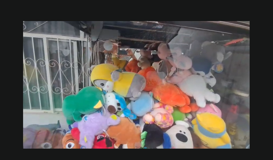
The machine-control path moves browser commands over MQTT to an ESP32, while the existing Firebase services continue to handle accounts, balances, payments and session records.
The physical machine used for integration and testing. Camera work remains ongoing.
System flow
The machine-control path
Use the browser controlsPress, hold or release a direction or grab control.
Send the commandMQTT over WebSocket carries the message through EMQX.
Handle it on ESP32Interpret the command and its session state.
Drive or stop the machineApply the movement, grab or stop command.
Technical notes and images
Retaining existing services
The migration retained Firebase for account and game records. Browser commands travel over MQTT and WebSocket through EMQX to the ESP32, which controls the machine's relay outputs. This let the control path change without rebuilding the surrounding application.
Movement and stop handling
The command handling covers direction, grab and stop. It distinguishes a short press from a held control, stops movement on release, and includes protection against stale or duplicate commands. A watchdog and failsafe behaviour address interrupted control sessions.
Machine testing
Client testing confirmed responsive machine control. Camera integration is being refined alongside the working control path.
Lighting and interaction / 12 records
Record 001 / Lighting and interaction
Interactive tic tac toe LED controller
Firmware development
LED game logic for player selection, matrix addressing and win detection. The project includes input debouncing and cell selection routines.
WS2812Embedded C++Game logicInput debouncing
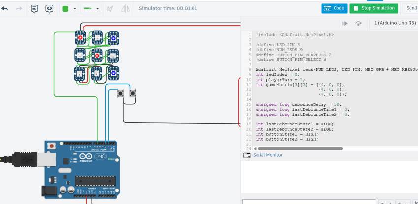
Project design or interface view — Interactive tic tac toe LED controllerTechnical notes and images
Input debouncing
The debounce() routine addresses the first interaction problem: a mechanical press can create several electrical transitions. Input conditioning belongs before game logic, where duplicate events could otherwise become duplicate moves.
Cell selection
traverseMatrix() and selectLED() separate matrix navigation from LED cell selection.
Win detection
checkWin() evaluates the game board separately from pixel updates.
Record 016 / Lighting and interaction
Addressable LED strip controller
Firmware development
Firmware for addressable LED strip output and lighting sequences.
WS2812Addressable LEDsEmbedded C++
Technical notes and images
Colour commands
setStripColor() applies a colour to the strip separately from the lower-level pixel transmission.
Clearing the output
clearStrip() provides a distinct operation for removing the current output.
Pixel and command timing
WS2812 output has its own signalling requirements. The firmware scope considers responsive lighting and command timing, so lighting sequences and input handling need to be considered together.
Record 030 / Lighting and interaction
ESP32 animated photo booth display
Firmware development
An ESP32 display application for animated photo booth feedback.
ESP32Display controlAnimation
Firmware flow
How a stored animation frame reaches the display
Selected monochrome frame rendering code.
Action · Repeat for all pixelsRead each stored frame bit
The application uses animation for photo-booth feedback.
Network and display interfaces
The application combines ESP32, Wi Fi and HTTP interfaces with display control, including text checks and grid data handling.
Display status
The development scope connects display logic with the photo booth’s user feedback.
Record 031 / Lighting and interaction
Lighting controller PCB layout concept
PCB layout concept
A PCB layout concept for a lighting controller, shown in a Fusion 360 routing view. The work concerns board connections, copper routing and the physical arrangement of the design.
Lighting patternsVisual prototyping
Technical notes and images
Circuit routing
The layout shows board connections and copper routing for the lighting controller.
Layout review
The Fusion 360 routing view shows the proposed lighting-controller layout.
Record 033 / Lighting and interaction
Keypad display and relay game controller
Firmware development
A game controller combining keypad input, visual feedback and relay outputs.
KeypadDisplayRelay controlGame logic
Technical notes and images
Keypad input
Input routines wait for a key and interpret individual choices according to the game state.
Menu and game state
Menu handling coordinates keypad choices with display feedback and relay actions.
Relay output
Relay outputs give the game a physical response alongside its visual feedback.
Record 037 / Lighting and interaction
Addressable lighting visualiser
Visual prototype
A visualisation prototype for addressable-lighting effects.
Addressable LEDsLighting visualisation
Technical notes and images
Lighting-effect visualisation
The visualiser shows how an effect occupies the lighting arrangement.
Prototype reference
The visual prototype illustrates addressable-lighting effects.
Record 038 / Lighting and interaction
Memory pattern LED game controller
Firmware development
A memory game using input sequences and LED feedback, with game state and pattern handling.
LED controlGame logicInput sequencing
Project design or interface view — Memory pattern LED game controllerTechnical notes and images
Pattern data
Pattern generation and membership checks represent the game sequence independently of the current LED output.
Pattern display and input
Separate routines display the LED pattern and read the player’s response.
Game logic and outputs
Game logic coordinates the stored pattern, LED presentation and player input.
Record 053 / Lighting and interaction
NeoPixel simulation and control sketch
Simulation and firmware
A simulation and control sketch for NeoPixel lighting sequences.
NeoPixelLED controlSimulation
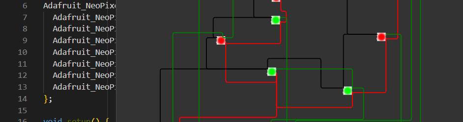
Project design or interface view — NeoPixel simulation and control sketchTechnical notes and images
Lighting sequence simulation
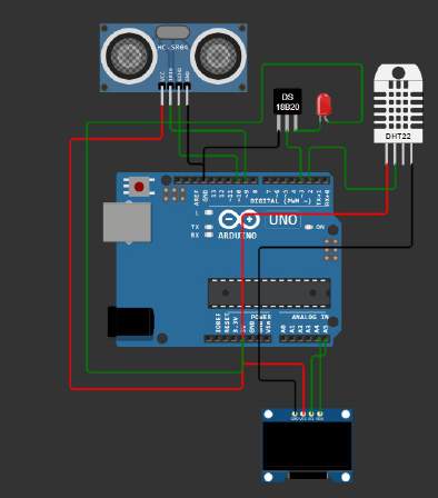
The simulation places the LED elements beside the control sketch, making it possible to relate the program to the colours and positions shown in the circuit view.
Power and signal wiring
The circuit view shows power and signal wiring alongside the LED elements and their logical arrangement.
Simulation stage
The simulation gives an early view of the lighting sequence and intended wiring. It supports review of the connections before the circuit moves to physical hardware.
Record 054 / Lighting and interaction
AbuLou SmartLED firmware
Firmware and prototype work
AbuLou SmartLED implements colour fades, stored scripts and motor patterns on an ATtiny85, controlled through a compact I2C command interface.
ATtiny85I2CRGB and HSVEEPROMMotor patternsNonblocking timing
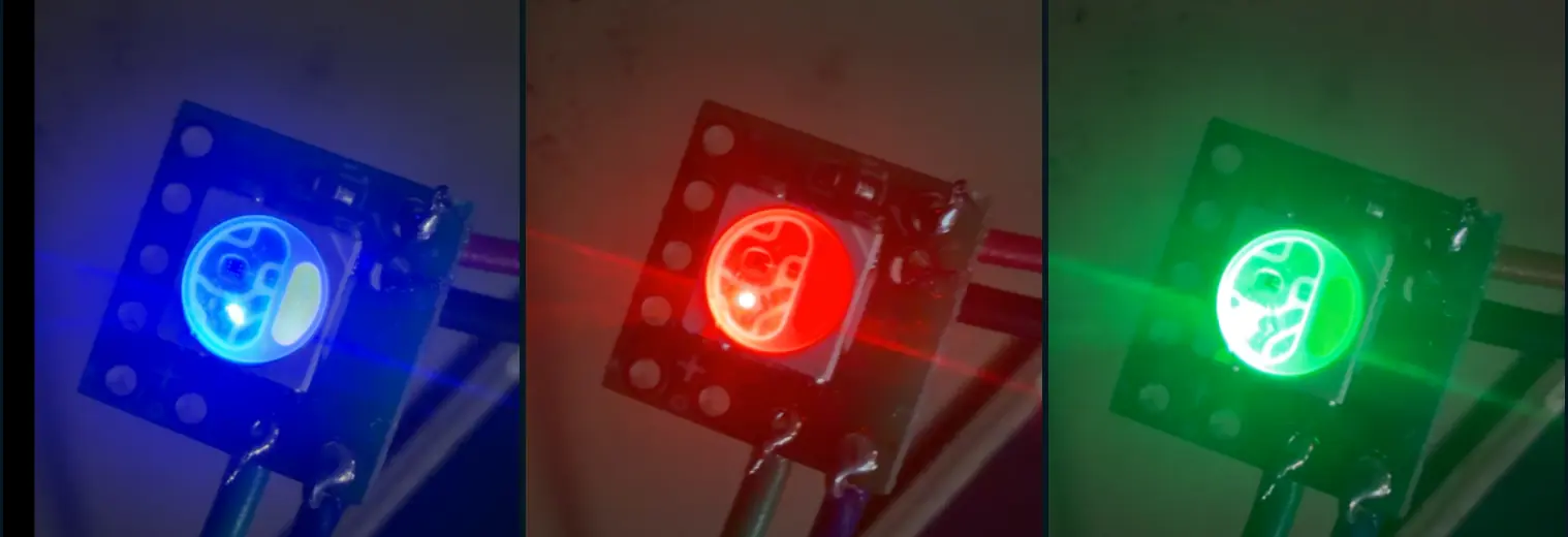
Photographs of illuminated prototype modules.
System flow
From command to output
Receive an I2C commandRead the requested colour, script or action.
Interpret the requestSelect the corresponding firmware function.
Update state and timingCoordinate fades, scripts and patterns.
Drive the outputUpdate the LED or motor pattern.
Technical notes and images
I2C command parsing
The interface uses BlinkM-style I2C commands. Packed command parsing links incoming instructions to RGB and HSV fades through a compact control interface.
EEPROM scripts
EEPROM-backed scripts keep programmed sequences available between sessions. The command engine stores the scripts, so an external application does not have to resend every lighting step.
Nonblocking updates
Animation and motor updates are organised without long blocking delays, so they do not occupy the controller at the expense of its command interface. Photographs show the small prototype modules illuminated in different colours.
Record 062 / Lighting and interaction
WS2812 animation controller
Firmware development
Animation control for WS2812 addressable LEDs.
WS2812LED animationEmbedded firmware
Technical notes and images
Shared colour updates
setAll() applies a common output state across the LEDs.
Animation sequences
Animation logic defines successive LED output states.
Lighting routines
The module provides lighting routines that produce the successive states of an addressable LED animation.
Record 085 / Lighting and interaction
EEPROM scripted LED controller
Firmware development
An addressable LED controller using stored scripts and local colour or animation selection routines.
EEPROMAddressable LEDsAnimation control
Technical notes and images
Stored lighting scripts
EEPROM provides storage for the lighting scripts. Keeping saved sequences separate from the code that executes them gives the controller a clear way to organise its lighting effects.
Local selection
The firmware includes ledCountMenu(), colorMenu() and colorCycle() routines. These connect user-facing choices, such as pixel count and colour, to the animation portion of the controller.
Pixel output
The output scope covers addressable LEDs, including WS2812 or NeoPixel-style control. Each saved or selected effect ultimately needs to be expressed as colour values across the configured pixels.
Record 093 / Lighting and interaction
Large format Bingo display
Firmware and hardware integration
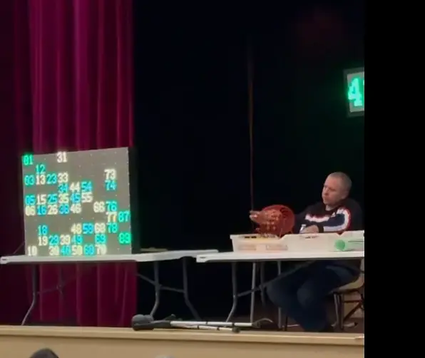
An ESP32 controls a large bingo display using WS2812 pixels. Wireless game updates select number highlights, with a pixel map linking each number to its panel position.
Result · List completeLeave the updated buffer ready
Accept only numbers from 1 to 90, look up the stored pixel list for that number and set those pixels to black in the LED buffer.
The routine updates the pixel buffer. It does not include the command that displays that buffer or establish installation size or frame rate.
Read the implementation
clearRows · selected source lines 156–167. Source inspection is not a hardware test.
// Clear rows for a specific number
void clearRows(int number) {
    if (number < 1 || number > 90) return;  // Ensure valid range STOP BLINK FOR MORE 90 !!!!!!

    int index = number - 1;  // Convert 1-based number to 0-based index
    int pixelCount = pgm_read_word(&numberPixelCount[index]);  // Read count from PROGMEM pgm_read_word (small)  or pgm_read_byte (original big)

    for (int i = 0; i < pixelCount; i++) {
        int pixelIndex = pgm_read_word(&numberPixels[index][i]);  // Read pixel index from PROGMEM
        strip.SetPixelColor(pixelIndex, blackColor);  // Turn off the pixel
    }
}
Incoming wireless updates drive changes in the displayed numbers. The firmware translates the relevant game state into lighting updates across the panels.
Pixel mapping
The display is organised as a large physical matrix, rather than a short decorative strip. A pixel map connects individual game numbers with the correct regions of the installed panels.
Firmware and panel integration
The work includes ESP32 firmware, display-state logic and integration with the physical LED installation. The visible result is a large-format number display in which selected regions carry the game information.
Sensing and instrumentation / 12 records
Record 006 / Sensing and instrumentation
IMU breathing motion analyser
Development work
An IMU based approach to observing breathing related motion. The project material covers sensor acquisition and motion data review.
IMUSensor acquisitionMotion sensing
Project design or interface view — IMU breathing motion analyserTechnical notes and images
Sensor placement
An IMU observes movement at its mounting point. Position and orientation therefore affect the signal being examined, which is an important consideration when relating motion to breathing.
Acquisition and review
I2C and UART support acquisition and data review, with the communication path kept distinct from the motion signal.
Measurement limits
The project concerns motion observation and analysis. Understanding that signal is a different task from establishing medical accuracy or diagnosing a condition; this work is an engineering exploration of movement.
Record 015 / Sensing and instrumentation
Environmental alarm and LCD controller
Firmware development
Environmental monitoring logic with threshold alarms and a local LCD interface.
Environmental sensingLCDAlarm logic
Technical notes and images
Sensor acquisition
Environmental input acquisition is separate from the threshold decisions that control the alarm.
Alarm thresholds
A threshold defines when the response should change. Making that rule explicit helps keep the displayed information and alarm response grounded in the same reading.
LCD updates
updateLCD() handles display refresh separately from the alarm decision logic.
Record 022 / Sensing and instrumentation
OLED cable test instrument
Development work
A cable testing interface presenting continuity information on a compact OLED display.
Continuity testingOLEDEmbedded control
Technical notes and images
Continuity test path
The continuity check relates the cable path being tested to the observed result.
OLED results
The OLED is the instrument’s local display for continuity results.
Test interface integration
I2C, UART and local controls support the test interface, separately from the continuity decision.
Record 036 / Sensing and instrumentation
Capacitive MIDI sensor interface
Firmware development
Capacitive sensor input translated into MIDI control information.
Capacitive sensingMIDIInput processing
Technical notes and images
Capacitive input processing
Input processing translates capacitive sensor readings into MIDI control events.
Message generation
The firmware scope includes MIDI message generation, UART communication and embedded C/C++.
Sensor-to-MIDI mapping
The scope connects capacitive input processing with MIDI output.
Record 049 / Sensing and instrumentation
Digital compass interface library
Firmware module
A compass interface library with magnetometer setup and heading readout routines.
HMC5883LMagnetometerI2CHeading data
Technical notes and images
I2C sensor interface
I2C connects the magnetic sensor with dedicated initialisation and heading-access routines.
Setup, heading and output
setupHMC5883L(), getHeading() and Output() separate sensor setup, heading acquisition and output.
Heading interpretation
A compass reading needs context: sensor orientation and the surrounding magnetic environment affect its meaning. Keeping acquisition separate from presentation gives the wider controller a clear place to apply its own operating conventions.
Record 050 / Sensing and instrumentation
Interrupt driven signal counter
Firmware module
Signal counting using interrupt driven input handling.
InterruptsEvent countingEmbedded firmware
Technical notes and images
Interrupt-based event capture
A polling loop only sees an input when execution reaches the read operation. Interrupt driven counting gives the input event its own response path instead of tying observation to the loop schedule.
Counter operation
The module accumulates incoming signal events into a count used by the application.
Capture and reporting timing
The useful distinction is between capturing an event and reporting the result. Output or communication activity should not determine when the system notices the next input transition.
Record 065 / Sensing and instrumentation
LiDAR start and finish timing modules
Firmware development
LiDAR measurements used in start and finish timing modules, with local timing and interface routines.
LiDARTimingEmbedded interface
Technical notes and images
Range detection events
LiDAR range information provides the input for start and finish event handling.
Application views and menus
drawApp(), drawMenu() and events() connect application views and menus with timing-event handling.
Time handling
getTime() handles the timing operation alongside detection, event handling and presentation.
Record 067 / Sensing and instrumentation
BLE load cell and compass prototype
Prototype development
A prototype combining load cell measurement, compass data and a BLE interface.
BLELoad cellMagnetometerI2C
Technical notes and images
Load-cell and compass measurements
A load cell and a magnetometer provide different information and require different interpretation. The prototype brings both into one application without treating their readings as interchangeable sensor values.
Sensor register access
writeRegister(), readRegister(), readMagnetometerData() and softReset() provide low-level sensor access.
BLE development platform
The development view identifies a Seeed XIAO BLE Sense nRF52840 target. BLE provides the wireless interface around the sensor work, while local diagnostics support inspection of the acquired data during development.
Record 087 / Sensing and instrumentation
IMU and LiDAR target guidance firmware
Prototype firmware
A handheld target-alignment prototype combines IMU orientation with LiDAR range measurements. The firmware brings the two inputs into a consistent update sequence before producing feedback.
Compare orientation with its tolerances and compare range only when both distance values exist. Choose target-reached, orientation-aligned or misaligned feedback, then update the LED and buzzer.
This classifies the readings against configured tolerances. It does not establish physical accuracy, safety performance or a tested acquisition range.
Read the implementation
alignment feedback excerpt · selected source lines 423–445. Source inspection is not a hardware test.
Orientation and range answer different questions about alignment. The IMU contributes the direction-related information, while the LiDAR contributes distance, giving the guidance application two complementary inputs to work with.
Acquisition loop
The firmware keeps inertial and range data within a consistent update sequence. The engineering concern is the relationship between those measurements when the handheld assembly changes position or orientation.
Feedback processing
Filtering and bias handling form part of the acquisition path. This adds a processing stage between raw sensor values and the feedback used by the target-alignment application.
Record 090 / Sensing and instrumentation
Blood oxygen sensor acquisition firmware
Sensor firmware
Firmware for acquiring readings from a blood oxygen sensor interface. Scope is sensor communication and data acquisition.
Sensor acquisitionI2CESP32
Technical notes and images
Sensor connection
I2C forms the communication link between the ESP32 and the sensor interface. The work concerns the firmware at that hardware boundary.
Data acquisition
The module focuses on obtaining sensor readings for further processing or reporting within the embedded application.
Interface scope
This is sensor communication work: the acquisition layer that connects a peripheral device with the controller’s application logic.
Record 091 / Sensing and instrumentation
Dual load cell measurement controller
Development work
A measurement controller for two load cell inputs, including channel handling and measurement processing.
Load cellsHX711Measurement firmware
Project design or interface view — Dual load cell measurement controllerTechnical notes and images
Two input channels
The controller’s scope includes two load-cell inputs. Keeping channel identity attached to a reading is a basic requirement for making sense of the measurements together.
Measurement processing
Firmware handles the measurements after acquisition through the load-cell interface. This is the application layer between incoming conversion data and the values used by the controller.
Hardware context
The accompanying controller material includes an ESP32 module schematic and a board view. These place the measurement firmware within a broader embedded hardware context.
Record 092 / Sensing and instrumentation
Dual channel HX711 load cell interface
Firmware module
An HX711 interface with channel selection and separate tare routines for two load cell channels.
HX711Load cellsChannel selectionTare
Project design or interface view — Dual channel HX711 load cell interfaceTechnical notes and images
Channel selection
selectChannelA() and selectChannelB() make input selection explicit in the source. This connects the firmware’s choice of channel to the measurement being requested from the interface.
Separate zero references
tareChannelA() and tareChannelB() provide separate tare operations. A tare action establishes a reference for its selected input, so the firmware must preserve the distinction between the two channels.
Wiring context
The wiring illustration brings two load cells, the interface board and a controller into one view. It complements the firmware by showing the physical inputs behind the channel operations.
Engineering studies / 8 records
Record 008 / Engineering studies
Round touchscreen interface concept
Interface concept
A user interface concept for a round touchscreen, covering screen layout and local interaction.
TouchscreenInterface design
Project design or interface view — Round touchscreen interface conceptTechnical notes and images
Circular screen layout
A rectangular screen layout cannot simply be cropped into a circle. Content near the perimeter has less horizontal room, so the shape influences hierarchy and placement.
Touch controls
The concept connects touch input with application screens within the available circular display area.
Screen navigation
Embedded C++ and state-based control provide the software context for the concept. Screen navigation is linked to device operation, with interface implementation left for later development.
Record 011 / Engineering studies
Heated enclosure control concept
Control concept
A control concept for managing a heated enclosure using environmental inputs and defined operating limits.
Temperature controlControl architecture
Technical notes and images
Environmental measurements
The concept relates environmental measurements to the desired operating range.
Control thresholds
Control and alarm thresholds define when the system should change its response.
Concept scope
The concept establishes inputs, state transitions and output responsibilities. These relationships allow the intended control logic to be reviewed before detailed hardware choices are made.
Record 014 / Engineering studies
Embedded systems technical assessment
Technical assessment
A technical assessment covering embedded requirements, interface considerations and engineering documentation.
Requirements analysisTechnical documentation
Technical notes and images
Requirements definition
An assessment needs to distinguish what the system is expected to do from the technology that might implement it. That separation keeps a component choice from becoming an unstated requirement.
Interface review
The assessment documents where system functions exchange information or depend on one another.
Record 018 / Engineering studies
Engineering solution design document
Design documentation
An engineering design document organising system requirements, interfaces and implementation choices.
System designRequirementsTechnical documentation
Technical notes and images
Requirements and design intent
Requirements describe what the system needs to do. Keeping them visible beside the design discussion helps prevent an implementation detail from changing the original objective.
Interface documentation
The document records how system parts exchange information, power and decisions.
Record 041 / Engineering studies
Arduino hardware integration plan
Integration planning
A hardware integration plan documenting an Arduino based system and its interfaces.
The plan defines wiring, interfaces and USB connections within an Arduino-based system.
Implementation reference
The interface documentation gives assembly and firmware work a common connection reference.
Record 070 / Engineering studies
Automated irrigation control architecture
Architecture study
An irrigation control architecture relating environmental inputs to pumps, valves and ventilation outputs.
Irrigation controlSystem architecturePumps and valves
Project design or interface view — Automated irrigation control architectureTechnical notes and images
Circulating water layout
The system illustration shows plant containers above a circulating water channel, with supply and overflow paths. This makes the physical process visible before the control logic is considered.
Environmental inputs and outputs
The architecture connects environmental information with scheduled pumps, valves and ventilation outputs. Each equipment type has a different role within the broader growing system.
Architecture study scope
The architecture study maps environmental inputs to pumps, valves and ventilation outputs.
Record 073 / Engineering studies
Sensor based fan control study
Design study
A design study for fan control using sensor input and operating requirements.
Fan controlSensor integrationDesign study
Project design or interface view — Sensor based fan control studyTechnical notes and images
Sensor inputs
The circuit illustration includes temperature, humidity and distance sensing around an Arduino Uno. These inputs describe different aspects of the local environment and should have clearly defined roles in a control application.
Local OLED feedback
An OLED display is shown in the same arrangement. A local view gives the system a place to present readings or operating information alongside the sensor connections.
Control study scope
This is a design study for sensor informed fan control. The sensing arrangement provides a foundation for discussing the intended response before a complete fan driver and operating strategy are settled.
Record 080 / Engineering studies
Wearable PCB and enclosure study
Design study
A study of electronics and mechanical fit for a smart ring concept, using a rigid-flex PCB within a constrained enclosure.
A ring offers a narrow, curved volume rather than a conventional flat board area. The study considers component placement in relation to that envelope and the space available around the wearer’s finger.
Rigid-flex concept
The PCB concept uses the ring geometry to organise the electronics. Rigid component regions and their connecting sections are considered together with enclosure shape, rather than resolving the circuit and mechanical package independently.
Board and enclosure fit
The CAD study shows the proposed board and enclosure arrangement. It examines the geometry and placement choices that shape later electrical and mechanical development.
No matching records.
Try a different term or clear the area filter.
Project enquiries
Discuss your project.
Tell us what you’re developing and where you need engineering support.