Sensing + prototype firmware
IMU and LiDAR alignment prototype
A handheld target-alignment prototype combines IMU orientation with LiDAR range measurements. The firmware brings the two inputs into a consistent update sequence before producing feedback.
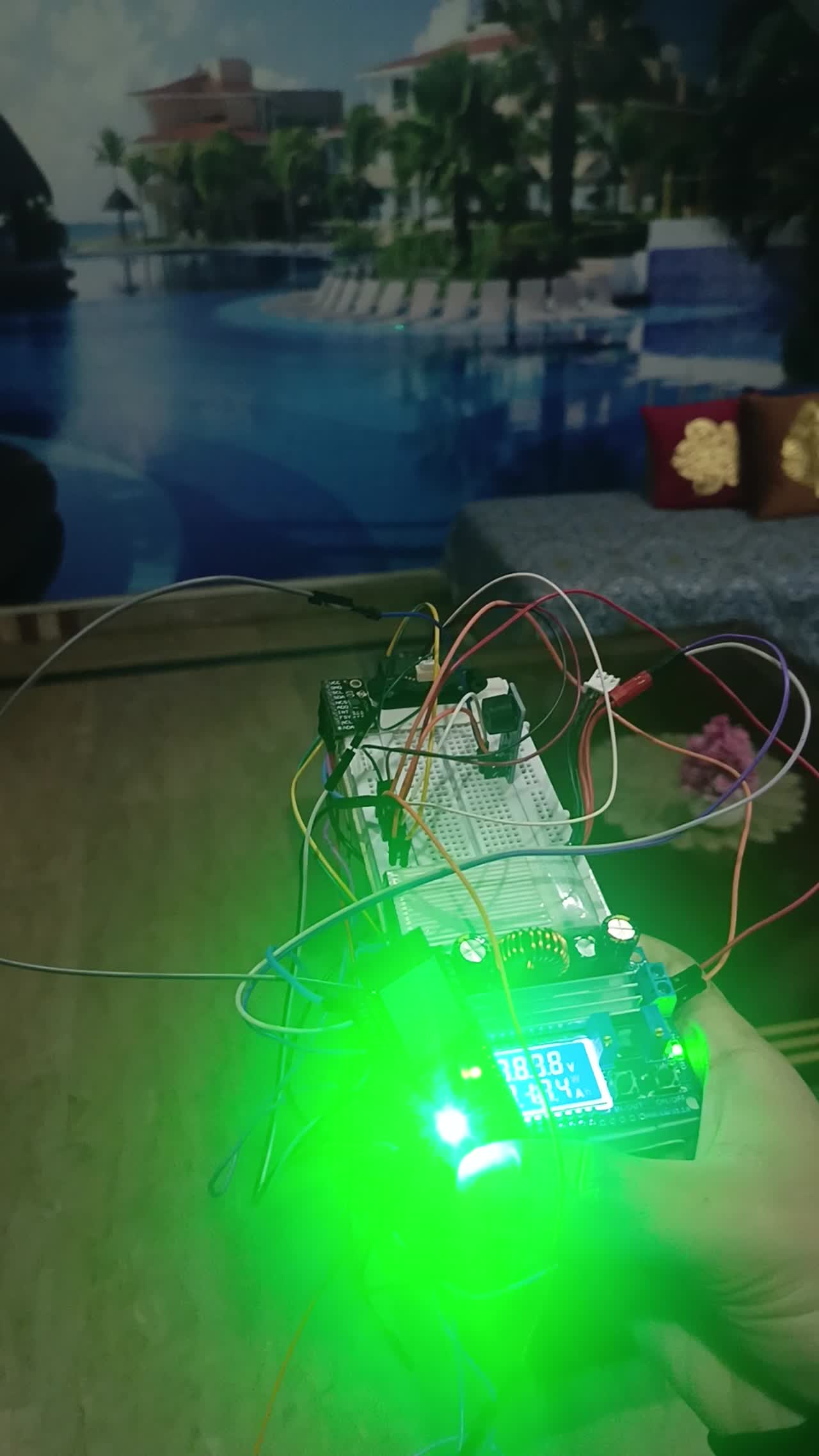
Engineering scope
- IMU orientation and LiDAR range acquisition
- A consistent sensor update sequence
- Filtering and bias handling before feedback
System flow
From two measurements to feedback
- Read orientationAcquire the IMU measurement.
- Read rangeAcquire the LiDAR distance.
- Process the measurementsApply filtering and bias handling.
- Update feedbackUse the processed values for target alignment.
Orientation and range inputs
The IMU provides orientation data and LiDAR measures distance. The alignment application uses both inputs to determine the feedback presented to the operator.
Acquisition and signal processing
The firmware reads inertial and range data in a consistent sequence. Filtering and bias handling process the raw measurements before they are used for feedback.
Prototype demonstration
The recording shows sensor acquisition and visible alignment feedback. Measured accuracy, field readiness and production validation are outside the documented scope.
Firmware flow
How the guidance prototype chooses feedback
Selected orientation and range alignment logic.
Compare orientation with its tolerances and compare range only when both distance values exist. Choose target-reached, orientation-aligned or misaligned feedback, then update the LED and buzzer.
This classifies the readings against configured tolerances. It does not establish physical accuracy, safety performance or a tested acquisition range.
Read the implementation
alignment feedback excerpt · selected source lines 423–445. Source inspection is not a hardware test.
  bool angAligned =
    (fabsf(errRoll)  <= ALIGN_ROLL_DEG)  &&
    (fabsf(errPitch) <= ALIGN_PITCH_DEG) &&
    (fabsf(errYaw)   <= ALIGN_YAW_DEG);

  bool distAligned = false;
  if (tfHasData && targetHasDist) {
    int32_t diff = (int32_t)tfDistCm - (int32_t)targetDistCm;
    if (diff < 0) diff = -diff;
    distAligned = (diff <= TARGET_DIST_TOL_CM);
  }

  if (angAligned && distAligned && tfHasData && targetHasDist) {
    trackState = TRACK_TARGET_REACHED;
  } else if (angAligned) {
    trackState = TRACK_LOCKED_ALIGNED;
  } else {
    trackState = TRACK_LOCKED_MISALIGNED;
  }

  updateLedForState();
  updateBuzzerForState();
}Prototype demonstration.
Original project recording · 1:31Project enquiries
Discuss your project.
Tell us what you’re developing and where you need engineering support.