PCB design + embedded firmware
CAN keypad and relay control
A two-board control system separates the operator’s keypad from the relay outputs. The handheld unit sends key events over CAN; the receiver maps each event to the corresponding relay.
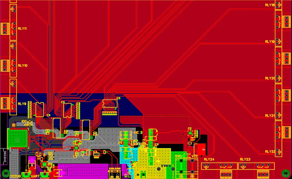
Engineering scope
- Transmitter and receiver PCB design
- Keypad scanning and CAN command handling
- Relay mapping for press and release events
System flow
How a key controls an output
- Read the keypadCapture the operator’s key event.
- Send a CAN commandCarry the event to the receiver.
- Map the commandChoose the corresponding relay output.
- Apply the outputUpdate the output for press or release.
Controller and receiver architecture
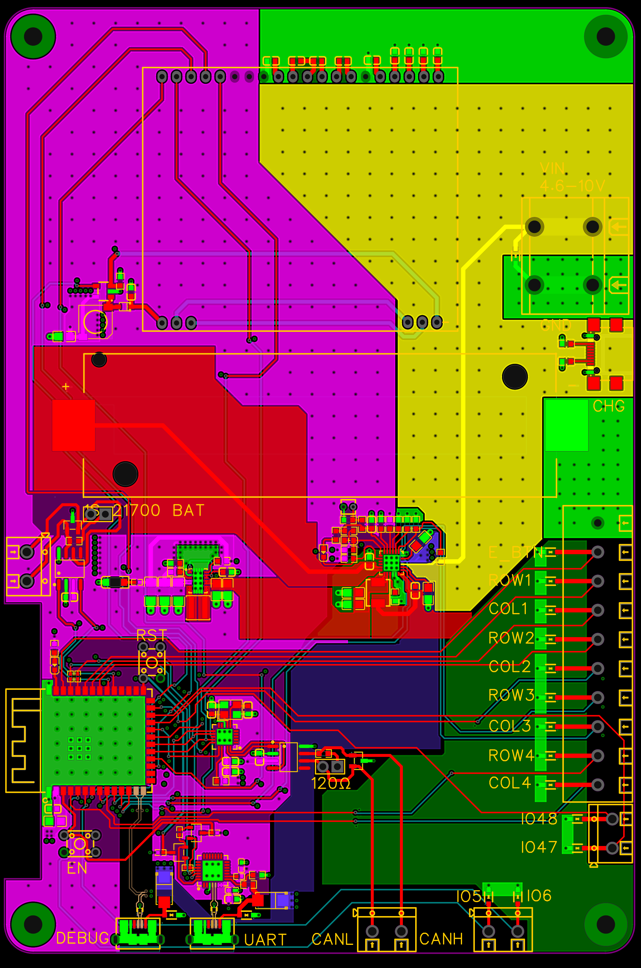
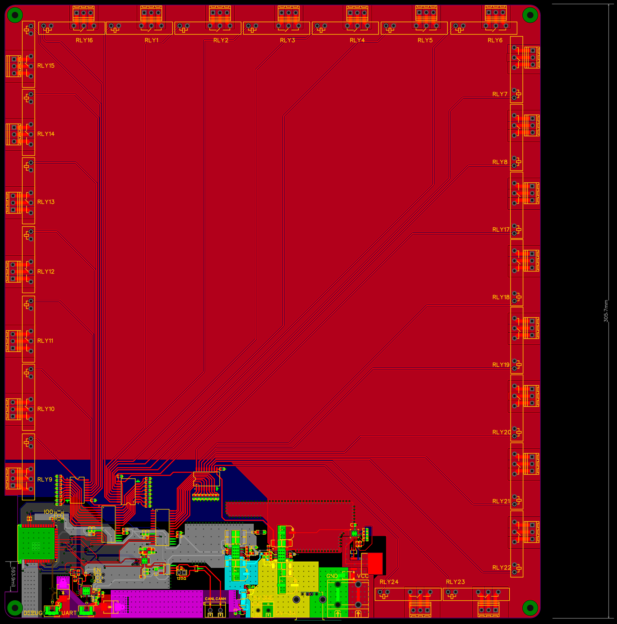
The handheld board handles keypad input near the operator. The receiver provides relay outputs near the actuators. CAN connects the two boards, separating input processing from output control.
Press and release handling
The firmware handles both key presses and releases. The receiver uses these events to start, change or stop the corresponding output.
PCB and interface design
The layouts document controller placement, CAN interfaces and output connections. PCB and firmware development are covered; completed hardware validation is not documented.
Project enquiries
Discuss your project.
Tell us what you’re developing and where you need engineering support.