Firmware flow
How a PWM output channel is configured
PWM timer and channel setup routine.
Allocate a timer for the requested frequency, configure the selected channel with zero initial duty, then keep the timer-to-channel mapping. Return failure if no timer is available or configuration fails.
This is setup code for one output channel. It does not show UDP transport, real-time timing performance or motor behaviour.
Read the implementation
configure_pwm_channel excerpt · selected source lines 47–70. Source inspection is not a hardware test.
bool configure_pwm_channel(int ch, int gpio, int freq) {
    ledc_timer_t timer = get_or_allocate_ledc_timer(freq);
    if (timer == (ledc_timer_t)-1)
        return false; // hiba: nincs szabad timer

    ledc_channel_config_t chan_cfg = {
        .gpio_num = gpio,
        .speed_mode = LEDC_HIGH_SPEED_MODE,
        .channel = (ledc_channel_t)ch,
        .intr_type = LEDC_INTR_DISABLE,
        .timer_sel = timer,
        .duty = 0,
        .hpoint = 0,
        .sleep_mode = LEDC_SLEEP_MODE_NO_ALIVE_NO_PD,
        .flags = {
            .output_invert = 0
        }
    };
    if (ledc_channel_config(&chan_cfg) != ESP_OK)
        return false;

    pwm_timer_map[ch] = timer;
    return true;
}Technical notes and images
Setpoint and pulse timing
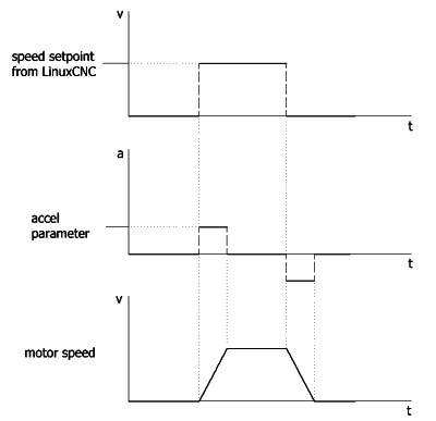
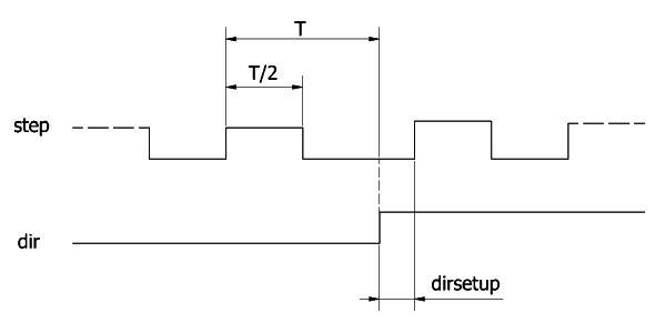
The reference drawings distinguish a LinuxCNC speed setpoint from the resulting motor speed, and show the relationship between step pulses and direction setup. These are different parts of the motion problem.
PWM configuration and updates
The firmware names configure_pwm_channel(), set_pwm_duty() and io_init(). This separates output preparation from later changes to the output value, making the hardware interface easier to follow.
UDP-to-hardware interface
UDP provides the communication side of the interface. The engineering work concerns how motion information reaches the hardware layer, without treating network message arrival as identical to a correctly timed motor signal.