Firmware example: recognising magnetic knob movement
Firmware flow
Firmware example: recognising magnetic knob movement
Separate two-input magnetic-knob firmware example; use on this four-channel PCB has not been established.
Compare the previous and current two-input states. Accept only a forward or reverse transition, optionally reverse its sign and accumulate it. Always remember the new state.
The selected variant has no timed Hall debounce or calibration. Accepted transitions contribute directly; they are not divided by four.
Read the implementation
Selected source excerpt · selected source lines 156–169. Source inspection is not a hardware test.
static inline void handleQuadEdge() {
  uint8_t sNew = readAB_normalized();
  uint8_t idx  = (prevState << 2) | sNew;
  int8_t step  = QEM[idx];

  if (step == 1 || step == -1) {
    if (REVERSE_DIR) step = -step;
    pending += step;
  }
  // ignore 0 or 2

  prevState = sNew;
  currState = sNew;
}Firmware example: turning knob movement into a tuning request
Firmware flow
Firmware example: turning knob movement into a tuning request
Separate two-input magnetic-knob tuning example; integration with this four-channel PCB has not been established.
Collect pending movement, update the offset and calculate a target frequency. If the result is beyond a band edge, wrap to the opposite boundary before requesting the tune.
The excerpt demonstrates the requested frequency calculation and boundary wrapping, not calibrated tuning accuracy or PCB operation.
Read the implementation
Selected source excerpt · selected source lines 236–257. Source inspection is not a hardware test.
  noInterrupts();
  int8_t d = pending;
  pending = 0;
  uint8_t s = currState;
  interrupts();

  if (d != 0) {
    totalSteps += d;
  }

  // 3) Compute target with wrap-around
  float target = baseMHz + totalSteps * STEP_MHZ;

  if (target > FM_MAX_MHZ + 1e-6f) {
    target = FM_MIN_MHZ;
    totalSteps = (int32_t) roundf((target - baseMHz) / STEP_MHZ);
  } else if (target < FM_MIN_MHZ - 1e-6f) {
    target = FM_MAX_MHZ;
    totalSteps = (int32_t) roundf((target - baseMHz) / STEP_MHZ);
  }

tuneTo(target);Technical notes and images
Hall transition decoding
The reviewed two-input version samples the A/B state when either input changes. It combines the previous and current states into a lookup-table index. Only +1 or −1 results change the pending count; unchanged states and invalid jumps are ignored. Direction can be reversed in configuration.
Frequency offset and wrapping
The main loop copies and clears the pending count with interrupts temporarily disabled. It adds that signed count to totalSteps, then requests baseMHz + totalSteps × 0.2 MHz. An out-of-band request wraps between 88 and 108 MHz. The code counts each accepted transition directly; it does not divide four transitions into one detent.
Filtering the potentiometer, not the Hall edges
The potentiometer uses an exponential moving average with alpha 0.15. Its base frequency changes only after a 0.05 MHz difference. This selected Hall decoder has no timed debounce gate. Other supplied variants use different decoding methods; their filename suffixes do not establish which was the final hardware version.
Board and firmware evidence
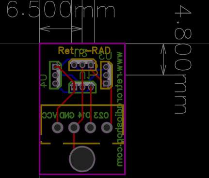
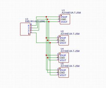
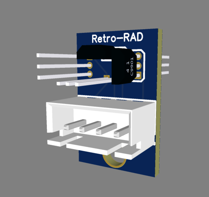
The original project record establishes a four-channel PCB design. The supplied example uses two digital Hall inputs to calculate an FM tuning request. The available files do not establish a connection between this firmware example and the pictured four-channel PCB.