Technical notes
Motion connections
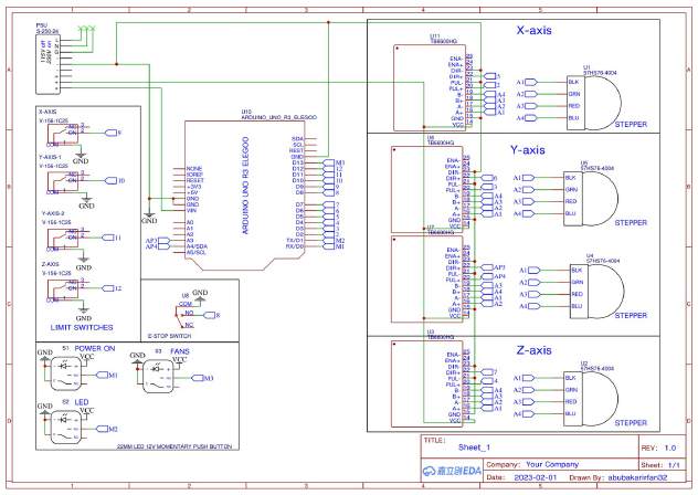
The drawing groups motor connections by axis. X and Z have their own sections, while the Y-axis section contains two stepper connections, making the machine’s motion wiring easier to follow.
Machine inputs
Limit switches and an emergency-stop connection are shown alongside the controller. Their placement in the same package makes these inputs part of the overall wiring discussion, rather than a separate installation note.
Assembly reference
Power, ground and control connections share the same drawing. For assembly and troubleshooting, the useful detail is the ability to trace a connection from the controller to the relevant driver, motor or input.