
PCB and firmware development
From a handheld key to a remote relay
A custom two board CAN system separates the operator keypad from the actuator outputs. The project combines PCB work with firmware that translates key events into commands for a relay receiver.
The brief
Separate a handheld keypad interface from the relay outputs that control external actuators.
Put the interface with the operator
The handheld side scans a keypad and translates user actions into CAN frames. This lets the control interface occupy a different physical location from the board connected to external actuators.
Keep the output mapping explicit
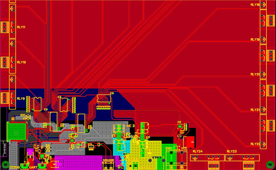
The receiver decodes the commands and applies a defined relay mapping. The layout image shows the output board's routing and relay connections, connecting the firmware task with the physical electrical interfaces.
Handle the end of an action
Key release is part of the command handling. A useful control interface must describe both the start of a requested action and the change when the operator releases the key.
What the evidence establishes
The project material documents the two-board design and its PCB/firmware development scope. The scope and status above describe the engineering work; they are not claims of mass production, certification, measured uptime or commercial returns.
Have a related engineering challenge?